

2 Physical Principles and Technical Aspects of Remote Sensing
31
[ii' 1 0 I:""""T'"-r-I"""'T"'-r-r-T".-........... ~
~
C
Q)
0
'0
lE
~ -10
()
en
.§ -20
Q)
~
ctI
~ -30 0
20
40
60
Angle of Incidence e [Degrees]
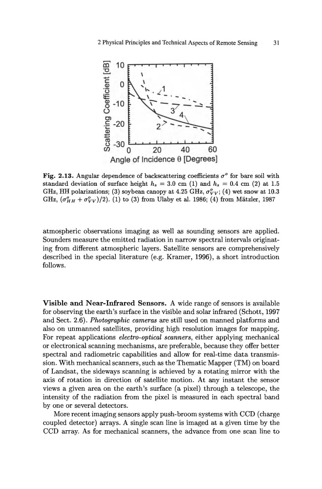
Fig. 2.13. Angular dependence of backscattering coefficients 0'0 for bare soil with
standard deviation of surface height hs = 3.0 em (1) and hs = 0.4 em (2) at 1.5
GHz, HH polarizations; (3) soybean canopy at 4.25 GHz, uvv; (4) wet snow at 10.3
GHz, (ullH + UVv )/2). (1) to (3) from Ulaby et al. 1986; (4) from Matzler, 1987
atmospheric observations imaging as well as sounding sensors are applied.
Sounders measure the emitted radiation in narrow spectral intervals originating from different atmospheric layers. Satellite sensors are comprehensively
described in the special literature (e.g. Kramer, 1996), a short introduction
follows.
Visible and Near-Infrared Sensors. A wide range of sensors is available
for observing the earth's surface in the visible and solar infrared (Schott, 1997
and Sect. 2.6). Photographic cameras are still used on manned platforms and
also on unmanned satellites, providing high resolution images for mapping.
For repeat applications electro-optical scanners, either applying mechanical
or electronical scanning mechanisms, are preferable, because they offer better
spectral and radiometric capabilities and allow for real-time data transmission. With mechanical scanners, such as the Thematic Mapper (TM) on board
of Landsat, the sideways scanning is achieved by a rotating mirror with the
axis of rotation in direction of satellite motion. At any instant the sensor
views a given area on the earth's surface (a pixel) through a telescope, the
intensity of the radiation from the pixel is measured in each spectral band
by one or several detectors.
More recent imaging sensors apply push-broom systems with CCD (charge
coupled detector) arrays. A single scan line is imaged at a given time by the
CCD array. As for mechanical scanners, the advance from one scan line to
31
[ii' 1 0 I:""""T'"-r-I"""'T"'-r-r-T".-........... ~
~
C
Q)
0
'0
lE
~ -10
()
en
.§ -20
Q)
~
ctI
~ -30 0
20
40
60
Angle of Incidence e [Degrees]
Fig. 2.13. Angular dependence of backscattering coefficients 0'0 for bare soil with
standard deviation of surface height hs = 3.0 em (1) and hs = 0.4 em (2) at 1.5
GHz, HH polarizations; (3) soybean canopy at 4.25 GHz, uvv; (4) wet snow at 10.3
GHz, (ullH + UVv )/2). (1) to (3) from Ulaby et al. 1986; (4) from Matzler, 1987
atmospheric observations imaging as well as sounding sensors are applied.
Sounders measure the emitted radiation in narrow spectral intervals originating from different atmospheric layers. Satellite sensors are comprehensively
described in the special literature (e.g. Kramer, 1996), a short introduction
follows.
Visible and Near-Infrared Sensors. A wide range of sensors is available
for observing the earth's surface in the visible and solar infrared (Schott, 1997
and Sect. 2.6). Photographic cameras are still used on manned platforms and
also on unmanned satellites, providing high resolution images for mapping.
For repeat applications electro-optical scanners, either applying mechanical
or electronical scanning mechanisms, are preferable, because they offer better
spectral and radiometric capabilities and allow for real-time data transmission. With mechanical scanners, such as the Thematic Mapper (TM) on board
of Landsat, the sideways scanning is achieved by a rotating mirror with the
axis of rotation in direction of satellite motion. At any instant the sensor
views a given area on the earth's surface (a pixel) through a telescope, the
intensity of the radiation from the pixel is measured in each spectral band
by one or several detectors.
More recent imaging sensors apply push-broom systems with CCD (charge
coupled detector) arrays. A single scan line is imaged at a given time by the
CCD array. As for mechanical scanners, the advance from one scan line to