

1 Introduction
9
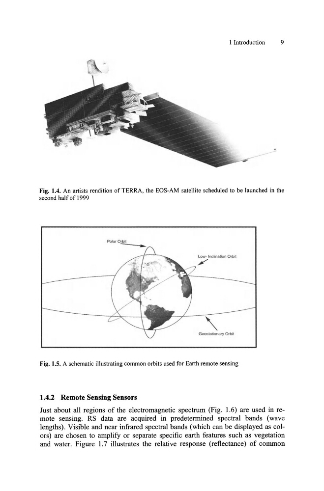
Fig. 1.4. An artists rendition of TERRA, the EOS-AM satellite scheduled to be launched in the
second half of 1999
Low· Inclination Orbil
,Geostationary Orbil
Fig. 1.5. A schematic illustrating common orbits used for Earth remote sensing
1.4.2 Remote Sensing Sensors
Just about all regions of the electromagnetic spectrum (Fig. 1.6) are used in remote sensing. RS data are acquired in predetermined spectral bands (wave
lengths). Visible and near infrared spectral bands (which can be displayed as colors) are chosen to amplify or separate specific earth features such as vegetation
and water. Figure 1.7 illustrates the relative response (reflectance) of common
9
Fig. 1.4. An artists rendition of TERRA, the EOS-AM satellite scheduled to be launched in the
second half of 1999
Low· Inclination Orbil
,Geostationary Orbil
Fig. 1.5. A schematic illustrating common orbits used for Earth remote sensing
1.4.2 Remote Sensing Sensors
Just about all regions of the electromagnetic spectrum (Fig. 1.6) are used in remote sensing. RS data are acquired in predetermined spectral bands (wave
lengths). Visible and near infrared spectral bands (which can be displayed as colors) are chosen to amplify or separate specific earth features such as vegetation
and water. Figure 1.7 illustrates the relative response (reflectance) of common