

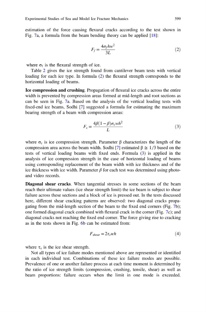
estimation of the force causing flexural cracks according to the test shown in
Fig. 7a, a formula from the beam bending theory can be applied [18]:
F f =
4σ f hw
2
3L
ð2Þ
where σ f is the flexural strength of ice.
Table 2 gives the ice strength found from cantilever beam tests with vertical
loading for each ice type. In formula (2) the flexural strength corresponds to the
horizontal loading of beams.
Ice compression and crushing. Propagation of flexural ice cracks across the entire
width is prevented by compression areas formed at mid-length and root sections as
can be seen in Fig. 7a. Based on the analysis of the vertical loading tests with
fixed-end ice beams, Sodhi [7] suggested a formula for estimating the maximum
bearing strength of a beam with compression areas:
F c =
4β 1 − β
ð
Þσ c wh
2
L
ð3Þ
where σ c is ice compression strength. Parameter β characterizes the length of the
compression area across the beam width. Sodhi [7] estimated β ≅ 1 ̸ 3 based on the
tests of vertical loading beams with fixed ends. Formula (3) is applied in the
analysis of ice compression strength in the case of horizontal loading of beams
using corresponding replacement of the beam width with ice thickness and of the
ice thickness with ice width. Parameter β for each test was determined using photoand video records.
Diagonal shear cracks. When tangential stresses in some sections of the beam
reach their ultimate values (ice shear strength limit) the ice beam is subject to shear
failure across these sections and a block of ice is pressed out. In the tests discussed
here, different shear cracking patterns are observed: two diagonal cracks propagating from the mid-length section of the beam to the fixed end corners (Fig. 7b);
one formed diagonal crack combined with flexural crack in the corner (Fig. 7c); and
diagonal cracks not reaching the fixed end corner. The force giving rise to cracking
as in the tests shown in Fig. 6b can be estimated from:
F shear = 2τ s wh
ð4Þ
where τ s is the ice shear strength.
Not all types of ice failure modes mentioned above are represented or identified
in each individual test. Combinations of these ice failure modes are possible.
Prevalence of one or another failure process at each time moment is determined by
the ratio of ice strength limits (compression, crushing, tensile, shear) as well as
beam proportions: failure occurs when the limit in one mode is exceeded.
Experimental Studies of Sea and Model Ice Fracture Mechanics
599