

188 Kikuro Miyakoda
R.tnftrrD SOt..uTtCft
(OF {9:) mEl
INCIIOI SOlllTJOli
( OF fp,} mEl
UUliAl COIi01TtOit
'ASSAGE THAOUCiH
w
"
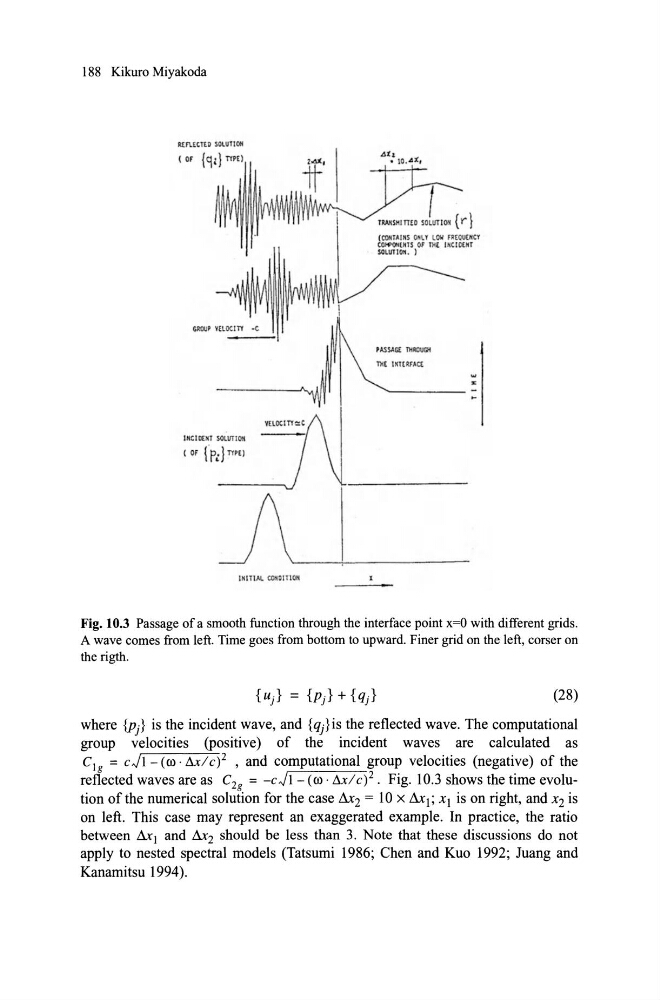
Fig. 10.3 Passage of a smooth function through the interface point x=O with different grids.
A wave comes from Ieft. Time goes from bottom to upward. Finer grid on the Ieft, corser on
the rigth.
(28)
where {Pj} is the incident wave, and {qj} is the reflected wave. The computational
group velocities (positive) of the incident waves are calculated as
C 1 g = C JI - (ro · D.x/ c)2 , and computational group velocities (negative) of the
reflected waves are as C 2g = - cJI- (ro · D.x/ c)2. Fig. 10.3 shows the time evolution ofthe numerical solution for the case &2 = 10 x &1; xI is on right, and x 2 is
on left. This case may represent an exaggerated example. In practice, the ratio
between & 1 and &2 should be less than 3. Note that these discussions do not
apply to nested spectral models (Tatsumi 1986; ehen and Kuo 1992; Juang and
Kanamitsu 1994).
R.tnftrrD SOt..uTtCft
(OF {9:) mEl
INCIIOI SOlllTJOli
( OF fp,} mEl
UUliAl COIi01TtOit
'ASSAGE THAOUCiH
w
"
Fig. 10.3 Passage of a smooth function through the interface point x=O with different grids.
A wave comes from Ieft. Time goes from bottom to upward. Finer grid on the Ieft, corser on
the rigth.
(28)
where {Pj} is the incident wave, and {qj} is the reflected wave. The computational
group velocities (positive) of the incident waves are calculated as
C 1 g = C JI - (ro · D.x/ c)2 , and computational group velocities (negative) of the
reflected waves are as C 2g = - cJI- (ro · D.x/ c)2. Fig. 10.3 shows the time evolution ofthe numerical solution for the case &2 = 10 x &1; xI is on right, and x 2 is
on left. This case may represent an exaggerated example. In practice, the ratio
between & 1 and &2 should be less than 3. Note that these discussions do not
apply to nested spectral models (Tatsumi 1986; ehen and Kuo 1992; Juang and
Kanamitsu 1994).