

Offshore Platforms 33.2 Types of Offshore Platforms 749
Part D | 33.2
Piles
Wells
Foundation
template
Hull or pontoon
Deck
Crane
Tower
Helideck
Columns
Tendon or tethers
Production risers
Water depth
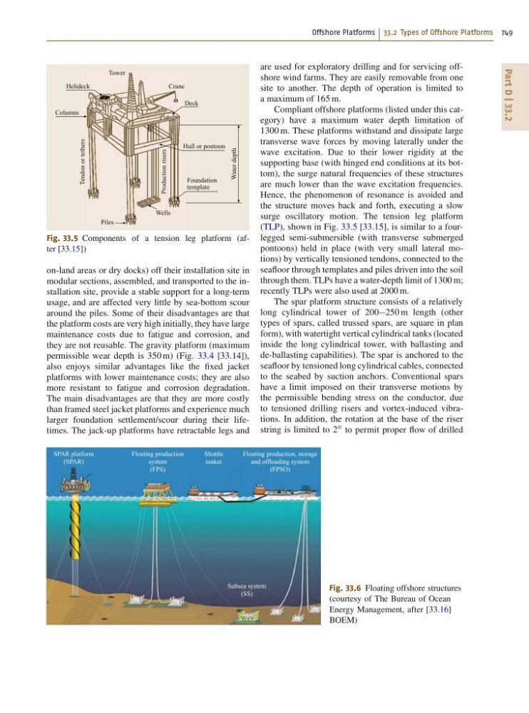
Fig. 33.5 Components of a tension leg platform (after [33.15])
on-land areas or dry docks) off their installation site in
modular sections, assembled, and transported to the installation site, provide a stable support for a long-term
usage, and are affected very little by sea-bottom scour
around the piles. Some of their disadvantages are that
the platform costs are very high initially, they have large
maintenance costs due to fatigue and corrosion, and
they are not reusable. The gravity platform (maximum
permissible wear depth is 350 m) (Fig. 33.4 [33.14]),
also enjoys similar advantages like the fixed jacket
platforms with lower maintenance costs; they are also
more resistant to fatigue and corrosion degradation.
The main disadvantages are that they are more costly
than framed steel jacket platforms and experience much
larger foundation settlement/scour during their lifetimes. The jack-up platforms have retractable legs and
SPAR platform
(SPAR)
Floating production
system
(FPS)
Shuttle
tanker
Floating production, storage
and offloading system
(FPSO)
Subsea system
(SS)
Fig. 33.6 Floating offshore structures
(courtesy of The Bureau of Ocean
Energy Management, after [33.16]
BOEM)
are used for exploratory drilling and for servicing offshore wind farms. They are easily removable from one
site to another. The depth of operation is limited to
a maximum of 165 m.
Compliant offshore platforms (listed under this category) have a maximum water depth limitation of
1300 m. These platforms withstand and dissipate large
transverse wave forces by moving laterally under the
wave excitation. Due to their lower rigidity at the
supporting base (with hinged end conditions at its bottom), the surge natural frequencies of these structures
are much lower than the wave excitation frequencies.
Hence, the phenomenon of resonance is avoided and
the structure moves back and forth, executing a slow
surge oscillatory motion. The tension leg platform
(TLP), shown in Fig. 33.5 [33.15], is similar to a fourlegged semi-submersible (with transverse submerged
pontoons) held in place (with very small lateral motions) by vertically tensioned tendons, connected to the
seafloor through templates and piles driven into the soil
through them. TLPs have a water-depth limit of 1300 m;
recently TLPs were also used at 2000 m.
The spar platform structure consists of a relatively
long cylindrical tower of 200250 m length (other
types of spars, called trussed spars, are square in plan
form), with watertight vertical cylindrical tanks (located
inside the long cylindrical tower, with ballasting and
de-ballasting capabilities). The spar is anchored to the
seafloor by tensioned long cylindrical cables, connected
to the seabed by suction anchors. Conventional spars
have a limit imposed on their transverse motions by
the permissible bending stress on the conductor, due
to tensioned drilling risers and vortex-induced vibrations. In addition, the rotation at the base of the riser
string is limited to 2
ı to permit proper flow of drilled