

Part C | 32.3
718 Part C Coastal Design
Table 32.2 Solutions to the governing asymptotic equations for positively buoyant plumes when the ambient current
speed is nonzero and the marine water density is linearly stratified (after [32.6]). Solutions to the asymptotic equations
are applicable only at the end of the near field and do not include the outlet port diameter, angle of discharge, or the exit
velocity
Axisymmetric source
Line source
z.x/ D
0:98
f
2=3
ent
Â
BSŒ1cos. Nx
U /
UN 2
à 1=3
z .x/ D
1:00
f
1=2
ent
Â
BSŒ1cos. Nx
U /
UN 2
à 1=2
2b .z/ D 2:00f ent z
2b .z/ D 2:00f ent z
.z/ D
CS
C.z/ D 3:14f 2
ent Uz 2 nports
Q
S .z/ D
CS
C.z/ D 2:00f ent Uz
LD
Q
z max D
1:24
f
2=3
ent
BS
UN 2
Á 1=3
z max D
1:41
f
1=2
ent
BS
UN 2
Á 1=2
2b .z max / D 2:48f
1=3
ent
BS
UN 2
Á 1=3
2b .z max / D 2:82f
1=2
ent
BS
UN 2
Á 1=2
S .z max / D
CS
C.zmax / D 4:84f
2=3
ent
Â
UB 2
S
N 4
à 1=3
nports
Q
S .z max / D
CS
C.zmax / D 2:83f
1=2
ent
UBS
N 2
Á 1=2 LD
Q
z is the elevation of the plume above the outlet [m], z max is the maximum elevation (i. e., height of rise) of the plume [m], S .z/ D
CS
C.z/
is the average dilution at elevation z, C S is the concentration at the source [kg=m
3 ], C .z/ is average concentration at elevation z
[kg=m
3 ], x is distance downstream from the outfall [m], f ent is the dimensionless entrainment function, U is ambient current velocity
[m=s], N is the Brunt–Väisälä frequency [1=s], where N
2 D
g
a
da
dz , and a denotes a representative seawater density, 2b.z/ is the
diameter (or thickness) of the plume [m], Q is the flow through the outfall [m 3 =s], L D is the length of the diffuser [m], n ports is the
total number of outlet ports on the diffuser and, B S is the buoyancy flux at the source, B S D g
aS
S
Q
nports for an axisymmetric source
and B S D g
a S
S
Q
LD for a line source, where S is the density of the wastewater at the source.
a spreading function to model the entrainment of ambient fluid into the plume.
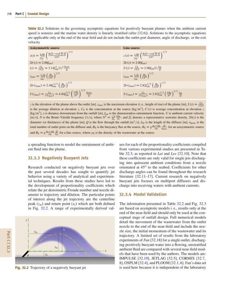
32.3.3 Negatively Buoyant Jets
Research conducted on negatively buoyant jets over
the past several decades has sought to quantify jet
behavior using a variety of analytical and experimental techniques. Results from these studies have led to
the development of proportionality coefficients which
relate the jet densimetric Froude number and nozzle diameter to trajectory and dilution. The particular points
of interest along the jet trajectory are the centerline
peak (z m / and return point (x r / which are both defined
in Fig. 32.2. A range of experimentally derived valθ
x m
x r
x
z t
z 0
z m
z
Fig. 32.2 Trajectory of a negatively buoyant jet
ues for each of the proportionality coefficients compiled
from various experimental studies are presented in Table 32.3, as reported in Lai and Lee [32.10]. Note that
these coefficients are only valid for single jets discharging into quiescent ambient conditions from a nozzle
orientated at 45
ı to the seabed. Coefficients for other
discharge angles can be found throughout the research
literature [32.11–17]. Current research on negatively
buoyant jets focuses on multiport diffusers and discharge into receiving waters with ambient currents.
32.3.4 Model Validation
The information presented in Table 32.2 and Fig. 32.3
are based on asymptotic models i. e., results only at the
end of the near-field and should only be used at the conceptual stage of outfall design. Full numerical models
detail the movement of the wastewater from the outlet
nozzle to the end of the near-field and include the nozzle size, the initial momentum of the wastewater and its
trajectory. A limited set of results from the laboratory
experiments of Fan [32.18] for a single outlet, discharging positively buoyant water into a flowing, unstratified
ambient fluid are compared with several near-field models that have been used by the authors. The models are:
IMPULSE [32.19], JETLAG [32.5], CORMIX [32.7,
8], OSPLM [32.4], and PLOOM [32.1, 6]. Fan’s data set
is used here because it is independent of the laboratory