

Storm Hazard Mitigation Structures 30.2 Coastal Armoring Structures 669
Part C | 30.2
: relative mass density .. s == w / 1
S: relative eroded area
P: permeability parameter
N z : number of waves
˛: structure slope angle
s m : wave steepness, s m D H s =L om
L om : deepwater wavelength corresponding to mean
wave period, T m .
These two formulae can be converted into design
equations with partial safety factors H and Z ; where
the hat symbol indicates mean values of the variable,
and each equation has its own table of partial safety
factors for the full range of failure probability P f and
wave height uncertainty
0 . The partial safety factors
are from [30.6] and [30.48]:
Plunging waves
G D
1
Z
6:2 O
S
0:2 O
P
0:18 O
O
D n O
f .cO ot //
0:5
.O s om /
0:25 O
N
0:1
Z
H O
H
T
S ;
(30.24)
with partial safety factors as displayed in Table 30.3.
Surging waves
G D
1
Z
O
S
0:2 O
P
0:13 O
O
D n O
f .cO ot //
0:5p
.O s om /
0:5P O
N
0:1
Z
H O
H
T
S ;
(30.25)
with partial safety factors as displayed in Table 30.4.
In these formulations for design use, the reduction
factor O
f models the effect of low crested, overtopped
Table 30.3 Partial safety factors (after [30.1, Table VI-65])
0
FHs
D 0:05
0
FHs
D 0:2
P f
H
Z
H
Z
0:01
1:6
1:04
1:9
1:00
0:05
1:4
1:02
1:5
1:06
0:10
1:3
1:00
1:3
1:10
0:20
1:2
1:00
1:2
1:06
0:40
1:0
1:08
1:0
1:10
Table 30.4 Partial safety factors (after [30.1, Table VI-66])
0
FHs
D 0:05
0
FHs
D 0:2
P f
H
Z
H
Z
0:01
1:7
1:00
1:9
1:02
0:05
1:3
1:10
1:6
1:00
0:10
1:3
1:02
1:4
1:04
0:20
1:1
1:10
1:2
1:08
0:40
1:0
1:08
1:1
1:00
breakwaters [30.49] and is given by the expression
O
f D
Â
1:25 4:8
R c
H s
r
s op
2
à 1
;
(30.26)
0 <
R c
H s
r
s op
2
< 0:052 :
(30.27)
Note that when the freeboard R c is zero, O
f reduces
to a minimum of 0.8 and when the argument
Rc
Hs
q
sop
2
reaches 0:052, there is no reduction in the stone size
since O
f D 1:0.
See also van der Meer [30.49] for the formulation
when the rock breakwater is completely submerged.
The overtopped and submerged cases do not always
give a smaller, lighter rock size for the armor layer.
Burchardt et al. [30.48] give an alternate method to
estimate the static stability of a detached, low-crested
breakwater.
For the G D Resistance – Load to be zero, the primary variables in these design equations are ( O
H
T
S , O
P, O
S,
N, T om , and cO ot /) for a given, stable rock size O
D n . The
rock mass is then simply . O
D n /
3 . In what follows, the
mean value (hat symbol) is assumed and the hat symbol
is omitted.
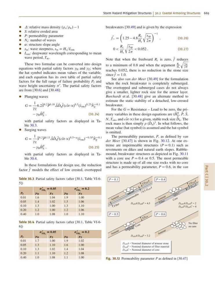
The permeability parameter, P, as defined by van
der Meer [30.47] is shown in Fig. 30.12. At one extreme are impermeable structures (P D 0:1) such as
revetments on dikes and natural earth slopes. Rubblemound, breakwater structures as depicted in Fig. 30.11
with a core use P D 0:4 or 0:5. The most permeable
structure is made up of all one size rocks with no core
and has a permeability parameter, P D 0:6, in the van
A r m o u r
2 D n 5 0
D n50 A/D n50 F = 4.5
D n50 A/D n50 F = 3.2
D n50 A = Nominal diameter of armour stone
D n50 F = Nominal diameter of filter material
D n50 C = Nominal diameter of core
I m p e r m e a b le
F il te r
A r m o u r
P = 0.1
2 D n 5 0 A
0 .5 D n 5 0 A
D n50 A/D n50 F = 2
D n50 F/D n50 C = 4
No filter
no care
C o r e
C o r e
F il te r
A r m o u r
A r m o u r
P = 0.4
P = 0.5
P = 0.6
2 D n 5 0 A
1 .5 D n 5 0 A
Fig. 30.12 Permeability parameter P as defined in [30.47]