

Part C | 30.2
668 Part C Coastal Design
Limit of wave runup
a)
b)
Limit of wave runup
Design high water
Design high water
Design low water
Design low water
Toe filter
Toe filter
Sub-base
Base
Core
Core
M/10
M/200
M/2
M/2
Secondary armor
layer
Secondary armor
layer
Primary armor layer
M a
M a
M
Primary armor layer
M a /10
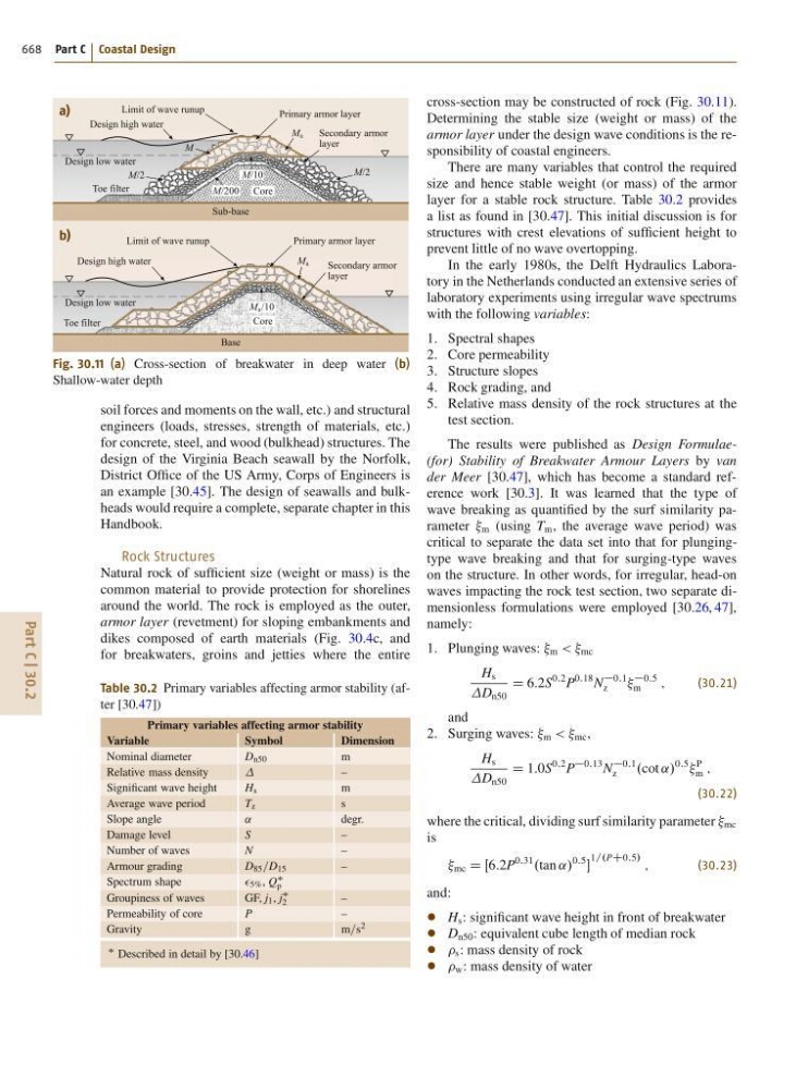
Fig. 30.11 (a) Cross-section of breakwater in deep water (b)
Shallow-water depth
soil forces and moments on the wall, etc.) and structural
engineers (loads, stresses, strength of materials, etc.)
for concrete, steel, and wood (bulkhead) structures. The
design of the Virginia Beach seawall by the Norfolk,
District Office of the US Army, Corps of Engineers is
an example [30.45]. The design of seawalls and bulkheads would require a complete, separate chapter in this
Handbook.
Rock Structures
Natural rock of sufficient size (weight or mass) is the
common material to provide protection for shorelines
around the world. The rock is employed as the outer,
armor layer (revetment) for sloping embankments and
dikes composed of earth materials (Fig. 30.4c, and
for breakwaters, groins and jetties where the entire
Table 30.2 Primary variables affecting armor stability (after [30.47])
Primary variables affecting armor stability
Variable
Symbol
Dimension
Nominal diameter
D n50
m
Relative mass density
–
Significant wave height
H s
m
Average wave period
T z
s
Slope angle
˛
degr.
Damage level
S
–
Number of waves
N
–
Armour grading
D 85 =D 15
–
Spectrum shape
5% , Q
p
Groupiness of waves
GF, j 1 , j
2
–
Permeability of core
P
–
Gravity
g
m=s 2
Described in detail by [30.46]
cross-section may be constructed of rock (Fig. 30.11).
Determining the stable size (weight or mass) of the
armor layer under the design wave conditions is the responsibility of coastal engineers.
There are many variables that control the required
size and hence stable weight (or mass) of the armor
layer for a stable rock structure. Table 30.2 provides
a list as found in [30.47]. This initial discussion is for
structures with crest elevations of sufficient height to
prevent little of no wave overtopping.
In the early 1980s, the Delft Hydraulics Laboratory in the Netherlands conducted an extensive series of
laboratory experiments using irregular wave spectrums
with the following variables:
1. Spectral shapes
2. Core permeability
3. Structure slopes
4. Rock grading, and
5. Relative mass density of the rock structures at the
test section.
The results were published as Design Formulae(for) Stability of Breakwater Armour Layers by van
der Meer [30.47], which has become a standard reference work [30.3]. It was learned that the type of
wave breaking as quantified by the surf similarity parameter m (using T m , the average wave period) was
critical to separate the data set into that for plungingtype wave breaking and that for surging-type waves
on the structure. In other words, for irregular, head-on
waves impacting the rock test section, two separate dimensionless formulations were employed [30.26, 47],
namely:
1. Plunging waves: m < < mc
H s
D n50
D 6:2S
0:2 P
0:18 N
0:1
z
0:5
m
;
(30.21)
and
2. Surging waves: m < < mc ,
H s
D n50
D 1:0S
0:2 P
0:13 N
0:1
z
.cot ˛/
0:5
P
m ;
(30.22)
where the critical, dividing surf similarity parameter mc
is
mc D Œ6:2P
0:31
.tan ˛/
0:5
1=.PC0:5/ ;
(30.23)
and:
H s : significant wave height in front of breakwater
D n50 : equivalent cube length of median rock
s : mass density of rock
w : mass density of water