

Part B | 17.6
418 Part B Autonomous Ocean Vehicles, Subsystems and Control
This is another important capability necessary to optimally set a roll and pitch configuration, as presented
by Marani et al. [17.50]. In fact, optimal positioning for
an I-AUV should minimize the energy consumption and
improve the stability in orientation. In general, during
an intervention task, the vehicle is maintained in a hovering configuration, thus requiring a 6 DOF control of the
vehicle positioning. The choice of roll and pitch, if done
arbitrarily, can severely impact the power efficiency of
the vehicle. This is especially significant in heavy systems, since the COB may not be necessarily aligned over
the COM. An EKF was used to identify the location
of the COB relative to the COM, making it possible to
compute the working orientation that maintains the COB
vertically aligned above the COM. The EKF was implemented online to detect any change in the COB caused
by various reasons, such as ballast operations. This approach helped achieve very precise position control of
the order of subcentimeter in translation.
17.6.5 Phase 5: Hook a Recovery Tool
to the Target Object
(Autonomous Manipulation)
The manipulator started searching for the target object
by using its optical camera mounted on the manipulator for short-range optical vision. Once the target object
and its location (6 DOF) were detected, the arm started
a tracking mode. After successfully locking on the target
object, it physically connected the recovery tool to the
target object. One important feature during this phase is
the workspace optimization. The vehicle is set to adjust
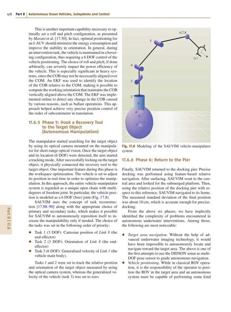
its position in real time in order to optimize the manipulation. In this approach, the entire vehicle-manipulator
system is regarded as a unique open chain with multidegrees of freedom joint. In particular, the vehicle position is modeled as a 6 DOF (free) joint (Fig. 17.8).
SAUVIM uses the concept of task reconstruction [17.88–90] along with the appropriate choice of
primary and secondary tasks, which makes it possible
for SAUVIM to autonomously reposition itself to increase the manipulability only if needed. The choice of
the tasks was set in the following order of priority:
Task 1 (3 DOF): Cartesian position of Link 8 (the
end-effector)
Task 2 (3 DOF): Orientation of Link 8 (the endeffector)
Task 3 (6 DOF): Generalized velocity of Link 1 (the
vehicle main body).
Tasks 1 and 2 were set to track the relative position
and orientation of the target object measured by using
the optical camera system, whereas the generalized velocity of the vehicle (task 3) was set to zero.
6,7,8
5
4
3
2
e
1
0
Fig. 17.8 Modeling of the SAUVIM vehicle-manipulator
system
17.6.6 Phase 6: Return to the Pier
Finally, SAUVIM returned to the docking pier. Precise
docking was performed using feature-based relative
navigation. After surfacing, SAUVIM went to the central area and looked for the submerged platform. Then,
using the relative position of the docking pier with respect to this reference, SAUVIM navigated to its home.
The measured standard deviation of the final position
was about 10 cm, which is accurate enough for precisedocking.
From the above six phases, we have implicitly
identified the complexity of problems encountered in
autonomous underwater interventions. Among those,
the following are most noticeable:
Target area navigation. Without the help of advanced underwater imaging technology, it would
have been impossible to autonomously locate and
navigate toward the target area. The above is one of
the first attempts to use the DIDSON sonar as multiDOF pose sensor to guide autonomous navigation.
Vehicle positioning. While in classical ROV operation, it is the responsibility of the operator to position the ROV in the target area and an autonomous
system must be capable of performing some kind
418 Part B Autonomous Ocean Vehicles, Subsystems and Control
This is another important capability necessary to optimally set a roll and pitch configuration, as presented
by Marani et al. [17.50]. In fact, optimal positioning for
an I-AUV should minimize the energy consumption and
improve the stability in orientation. In general, during
an intervention task, the vehicle is maintained in a hovering configuration, thus requiring a 6 DOF control of the
vehicle positioning. The choice of roll and pitch, if done
arbitrarily, can severely impact the power efficiency of
the vehicle. This is especially significant in heavy systems, since the COB may not be necessarily aligned over
the COM. An EKF was used to identify the location
of the COB relative to the COM, making it possible to
compute the working orientation that maintains the COB
vertically aligned above the COM. The EKF was implemented online to detect any change in the COB caused
by various reasons, such as ballast operations. This approach helped achieve very precise position control of
the order of subcentimeter in translation.
17.6.5 Phase 5: Hook a Recovery Tool
to the Target Object
(Autonomous Manipulation)
The manipulator started searching for the target object
by using its optical camera mounted on the manipulator for short-range optical vision. Once the target object
and its location (6 DOF) were detected, the arm started
a tracking mode. After successfully locking on the target
object, it physically connected the recovery tool to the
target object. One important feature during this phase is
the workspace optimization. The vehicle is set to adjust
its position in real time in order to optimize the manipulation. In this approach, the entire vehicle-manipulator
system is regarded as a unique open chain with multidegrees of freedom joint. In particular, the vehicle position is modeled as a 6 DOF (free) joint (Fig. 17.8).
SAUVIM uses the concept of task reconstruction [17.88–90] along with the appropriate choice of
primary and secondary tasks, which makes it possible
for SAUVIM to autonomously reposition itself to increase the manipulability only if needed. The choice of
the tasks was set in the following order of priority:
Task 1 (3 DOF): Cartesian position of Link 8 (the
end-effector)
Task 2 (3 DOF): Orientation of Link 8 (the endeffector)
Task 3 (6 DOF): Generalized velocity of Link 1 (the
vehicle main body).
Tasks 1 and 2 were set to track the relative position
and orientation of the target object measured by using
the optical camera system, whereas the generalized velocity of the vehicle (task 3) was set to zero.
6,7,8
5
4
3
2
e
1
0
Fig. 17.8 Modeling of the SAUVIM vehicle-manipulator
system
17.6.6 Phase 6: Return to the Pier
Finally, SAUVIM returned to the docking pier. Precise
docking was performed using feature-based relative
navigation. After surfacing, SAUVIM went to the central area and looked for the submerged platform. Then,
using the relative position of the docking pier with respect to this reference, SAUVIM navigated to its home.
The measured standard deviation of the final position
was about 10 cm, which is accurate enough for precisedocking.
From the above six phases, we have implicitly
identified the complexity of problems encountered in
autonomous underwater interventions. Among those,
the following are most noticeable:
Target area navigation. Without the help of advanced underwater imaging technology, it would
have been impossible to autonomously locate and
navigate toward the target area. The above is one of
the first attempts to use the DIDSON sonar as multiDOF pose sensor to guide autonomous navigation.
Vehicle positioning. While in classical ROV operation, it is the responsibility of the operator to position the ROV in the target area and an autonomous
system must be capable of performing some kind