

Part B | 15.4
368 Part B Autonomous Ocean Vehicles, Subsystems and Control
–0.5 0 0.5 1 1.5 2 2.5 3 3.5 4 4.5 5
Nominal path gains
Delay (ms)
1
0.8
0.6
0.4
0.2
0
–0.2
–0.4
–0.6
–0.8
–1
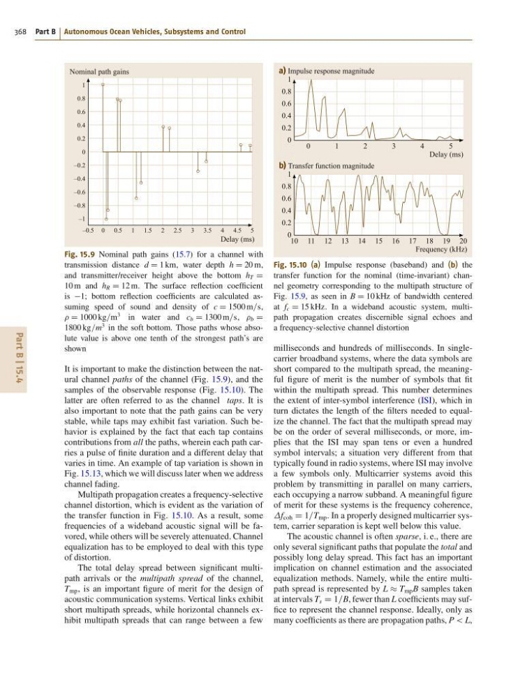
Fig. 15.9 Nominal path gains (15.7) for a channel with
transmission distance d D 1 km, water depth h D 20 m,
and transmitter/receiver height above the bottom h T D
10 m and h R D 12 m. The surface reflection coefficient
is 1; bottom reflection coefficients are calculated assuming speed of sound and density of c D 1500 m=s,
D 1000 kg=m
3 in water and c b D 1300 m=s, b D
1800 kg=m
3 in the soft bottom. Those paths whose absolute value is above one tenth of the strongest path’s are
shown
It is important to make the distinction between the natural channel paths of the channel (Fig. 15.9), and the
samples of the observable response (Fig. 15.10). The
latter are often referred to as the channel taps. It is
also important to note that the path gains can be very
stable, while taps may exhibit fast variation. Such behavior is explained by the fact that each tap contains
contributions from all the paths, wherein each path carries a pulse of finite duration and a different delay that
varies in time. An example of tap variation is shown in
Fig. 15.13, which we will discuss later when we address
channel fading.
Multipath propagation creates a frequency-selective
channel distortion, which is evident as the variation of
the transfer function in Fig. 15.10. As a result, some
frequencies of a wideband acoustic signal will be favored, while others will be severely attenuated. Channel
equalization has to be employed to deal with this type
of distortion.
The total delay spread between significant multipath arrivals or the multipath spread of the channel,
T mp , is an important figure of merit for the design of
acoustic communication systems. Vertical links exhibit
short multipath spreads, while horizontal channels exhibit multipath spreads that can range between a few
0
1
2
3
4
5
a) Impulse response magnitude
Delay (ms)
1
0.8
0.6
0.4
0.2
0
10 11 12 13 14 15 16 17 18 19 20
b) Transfer function magnitude
Frequency (kHz)
1
0.8
0.6
0.4
0.2
0
Fig. 15.10 (a) Impulse response (baseband) and (b) the
transfer function for the nominal (time-invariant) channel geometry corresponding to the multipath structure of
Fig. 15.9, as seen in B D 10 kHz of bandwidth centered
at f c D 15 kHz. In a wideband acoustic system, multipath propagation creates discernible signal echoes and
a frequency-selective channel distortion
milliseconds and hundreds of milliseconds. In singlecarrier broadband systems, where the data symbols are
short compared to the multipath spread, the meaningful figure of merit is the number of symbols that fit
within the multipath spread. This number determines
the extent of inter-symbol interference (ISI), which in
turn dictates the length of the filters needed to equalize the channel. The fact that the multipath spread may
be on the order of several milliseconds, or more, implies that the ISI may span tens or even a hundred
symbol intervals; a situation very different from that
typically found in radio systems, where ISI may involve
a few symbols only. Multicarrier systems avoid this
problem by transmitting in parallel on many carriers,
each occupying a narrow subband. A meaningful figure
of merit for these systems is the frequency coherence,
f coh D 1=T mp . In a properly designed multicarrier system, carrier separation is kept well below this value.
The acoustic channel is often sparse, i. e., there are
only several significant paths that populate the total and
possibly long delay spread. This fact has an important
implication on channel estimation and the associated
equalization methods. Namely, while the entire multipath spread is represented by L T mp B samples taken
at intervals T s D 1=B, fewer than L coefficients may suffice to represent the channel response. Ideally, only as
many coefficients as there are propagation paths, P < L,
368 Part B Autonomous Ocean Vehicles, Subsystems and Control
–0.5 0 0.5 1 1.5 2 2.5 3 3.5 4 4.5 5
Nominal path gains
Delay (ms)
1
0.8
0.6
0.4
0.2
0
–0.2
–0.4
–0.6
–0.8
–1
Fig. 15.9 Nominal path gains (15.7) for a channel with
transmission distance d D 1 km, water depth h D 20 m,
and transmitter/receiver height above the bottom h T D
10 m and h R D 12 m. The surface reflection coefficient
is 1; bottom reflection coefficients are calculated assuming speed of sound and density of c D 1500 m=s,
D 1000 kg=m
3 in water and c b D 1300 m=s, b D
1800 kg=m
3 in the soft bottom. Those paths whose absolute value is above one tenth of the strongest path’s are
shown
It is important to make the distinction between the natural channel paths of the channel (Fig. 15.9), and the
samples of the observable response (Fig. 15.10). The
latter are often referred to as the channel taps. It is
also important to note that the path gains can be very
stable, while taps may exhibit fast variation. Such behavior is explained by the fact that each tap contains
contributions from all the paths, wherein each path carries a pulse of finite duration and a different delay that
varies in time. An example of tap variation is shown in
Fig. 15.13, which we will discuss later when we address
channel fading.
Multipath propagation creates a frequency-selective
channel distortion, which is evident as the variation of
the transfer function in Fig. 15.10. As a result, some
frequencies of a wideband acoustic signal will be favored, while others will be severely attenuated. Channel
equalization has to be employed to deal with this type
of distortion.
The total delay spread between significant multipath arrivals or the multipath spread of the channel,
T mp , is an important figure of merit for the design of
acoustic communication systems. Vertical links exhibit
short multipath spreads, while horizontal channels exhibit multipath spreads that can range between a few
0
1
2
3
4
5
a) Impulse response magnitude
Delay (ms)
1
0.8
0.6
0.4
0.2
0
10 11 12 13 14 15 16 17 18 19 20
b) Transfer function magnitude
Frequency (kHz)
1
0.8
0.6
0.4
0.2
0
Fig. 15.10 (a) Impulse response (baseband) and (b) the
transfer function for the nominal (time-invariant) channel geometry corresponding to the multipath structure of
Fig. 15.9, as seen in B D 10 kHz of bandwidth centered
at f c D 15 kHz. In a wideband acoustic system, multipath propagation creates discernible signal echoes and
a frequency-selective channel distortion
milliseconds and hundreds of milliseconds. In singlecarrier broadband systems, where the data symbols are
short compared to the multipath spread, the meaningful figure of merit is the number of symbols that fit
within the multipath spread. This number determines
the extent of inter-symbol interference (ISI), which in
turn dictates the length of the filters needed to equalize the channel. The fact that the multipath spread may
be on the order of several milliseconds, or more, implies that the ISI may span tens or even a hundred
symbol intervals; a situation very different from that
typically found in radio systems, where ISI may involve
a few symbols only. Multicarrier systems avoid this
problem by transmitting in parallel on many carriers,
each occupying a narrow subband. A meaningful figure
of merit for these systems is the frequency coherence,
f coh D 1=T mp . In a properly designed multicarrier system, carrier separation is kept well below this value.
The acoustic channel is often sparse, i. e., there are
only several significant paths that populate the total and
possibly long delay spread. This fact has an important
implication on channel estimation and the associated
equalization methods. Namely, while the entire multipath spread is represented by L T mp B samples taken
at intervals T s D 1=B, fewer than L coefficients may suffice to represent the channel response. Ideally, only as
many coefficients as there are propagation paths, P < L,