

Part B | 14.1
344 Part B Autonomous Ocean Vehicles, Subsystems and Control
The power consumption and size of common optical
gyroscopes have limited their use to larger and more
expensive AUVs [14.1].
14.1.4 Attitude Heading Reference Systems
An attitude-heading reference system (AHRS) unit typically consists of a 3-axis gyroscope as well as a 3-axis
linear acceleration sensor and a heading sensor (magnetic or gyrocompass). Combining the measurements
from these sensors, the AHRS maintains a common
algorithmic orientation estimate between the sensor
cluster and the global world navigation frame. The
orientation is maintained through integration of the gyroscope measured rotation rates. Long term pitch and
roll stability of the orientation estimate is achieved
through selective use of earth’s gravity vector, which is
measured by a triad of accelerometers. The long-term
heading accuracy is maintained from either magnetic
compass sensor readings or direct measurement of the
earth rotation through the gyroscopes.
14.1.5 Inertial Navigation Systems
The sensors of an INS are the same as those of the
AHRS described earlier. In addition to the AHRS,
measured accelerations are rotated to the common navigation frame, as discussed above, and then double
integrated to compute a position estimate for the vehicle. The initial position of the INS is obtained from
an absolute position sensor (such as GPS or LBL). The
process of inertial navigation is discussed in more detail
in Sect. 14.2.1.
14.1.6 GPS
Almost all underwater vehicles today are equipped with
a GPS receiver as it can be used to get a position fix
before the start of the mission or during intermittent
surfacings. GPS measurements obtained at different
points during a mission can be used to constrain the error growth of position estimates derived from inertial
and Doppler sensors [14.3]. Farrell provides a comprehensive summary of the mathematical techniques for
a)
b)
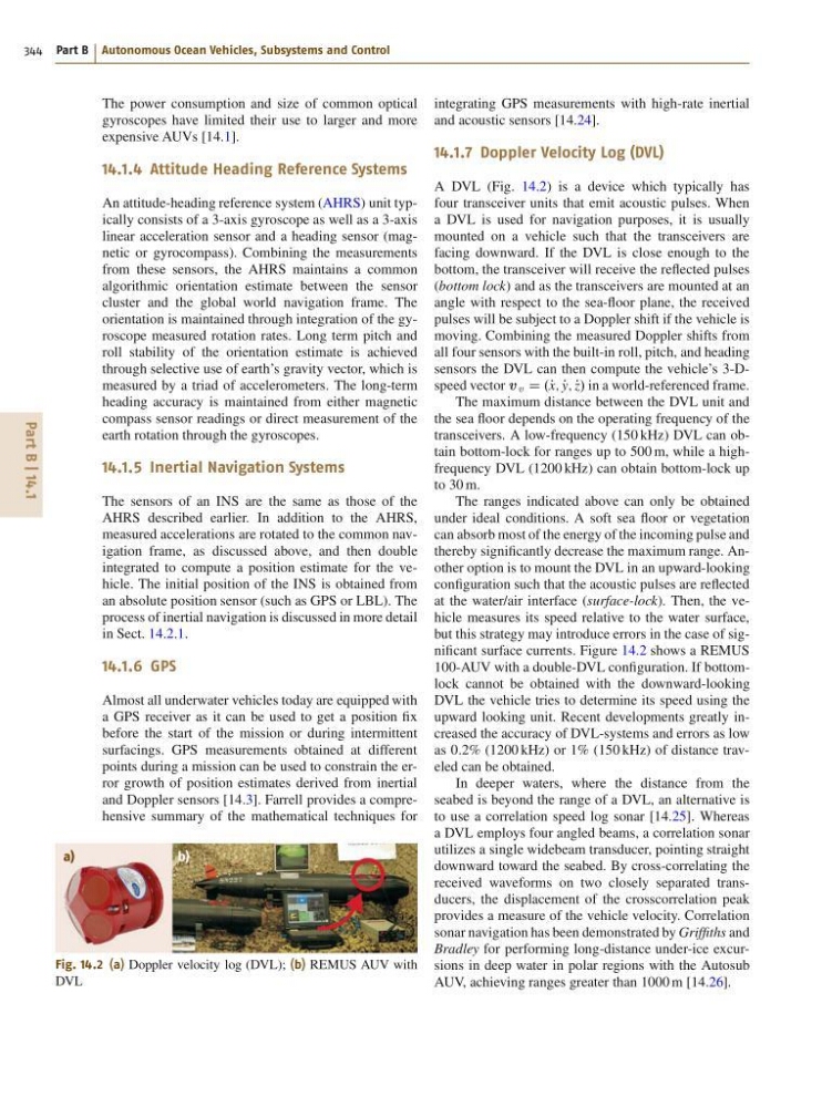
Fig. 14.2 (a) Doppler velocity log (DVL); (b) REMUS AUV with
DVL
integrating GPS measurements with high-rate inertial
and acoustic sensors [14.24].
14.1.7 Doppler Velocity Log (DVL)
A DVL (Fig. 14.2) is a device which typically has
four transceiver units that emit acoustic pulses. When
a DVL is used for navigation purposes, it is usually
mounted on a vehicle such that the transceivers are
facing downward. If the DVL is close enough to the
bottom, the transceiver will receive the reflected pulses
(bottom lock) and as the transceivers are mounted at an
angle with respect to the sea-floor plane, the received
pulses will be subject to a Doppler shift if the vehicle is
moving. Combining the measured Doppler shifts from
all four sensors with the built-in roll, pitch, and heading
sensors the DVL can then compute the vehicle’s 3-Dspeed vector v v D .P x; P
y; P
z/ in a world-referenced frame.
The maximum distance between the DVL unit and
the sea floor depends on the operating frequency of the
transceivers. A low-frequency (150 kHz) DVL can obtain bottom-lock for ranges up to 500 m, while a highfrequency DVL (1200 kHz) can obtain bottom-lock up
to 30 m.
The ranges indicated above can only be obtained
under ideal conditions. A soft sea floor or vegetation
can absorb most of the energy of the incoming pulse and
thereby significantly decrease the maximum range. Another option is to mount the DVL in an upward-looking
configuration such that the acoustic pulses are reflected
at the water/air interface (surface-lock). Then, the vehicle measures its speed relative to the water surface,
but this strategy may introduce errors in the case of significant surface currents. Figure 14.2 shows a REMUS
100-AUV with a double-DVL configuration. If bottomlock cannot be obtained with the downward-looking
DVL the vehicle tries to determine its speed using the
upward looking unit. Recent developments greatly increased the accuracy of DVL-systems and errors as low
as 0:2% (1200 kHz) or 1% (150 kHz) of distance traveled can be obtained.
In deeper waters, where the distance from the
seabed is beyond the range of a DVL, an alternative is
to use a correlation speed log sonar [14.25]. Whereas
a DVL employs four angled beams, a correlation sonar
utilizes a single widebeam transducer, pointing straight
downward toward the seabed. By cross-correlating the
received waveforms on two closely separated transducers, the displacement of the crosscorrelation peak
provides a measure of the vehicle velocity. Correlation
sonar navigation has been demonstrated by Griffiths and
Bradley for performing long-distance under-ice excursions in deep water in polar regions with the Autosub
AUV, achieving ranges greater than 1000 m [14.26].
344 Part B Autonomous Ocean Vehicles, Subsystems and Control
The power consumption and size of common optical
gyroscopes have limited their use to larger and more
expensive AUVs [14.1].
14.1.4 Attitude Heading Reference Systems
An attitude-heading reference system (AHRS) unit typically consists of a 3-axis gyroscope as well as a 3-axis
linear acceleration sensor and a heading sensor (magnetic or gyrocompass). Combining the measurements
from these sensors, the AHRS maintains a common
algorithmic orientation estimate between the sensor
cluster and the global world navigation frame. The
orientation is maintained through integration of the gyroscope measured rotation rates. Long term pitch and
roll stability of the orientation estimate is achieved
through selective use of earth’s gravity vector, which is
measured by a triad of accelerometers. The long-term
heading accuracy is maintained from either magnetic
compass sensor readings or direct measurement of the
earth rotation through the gyroscopes.
14.1.5 Inertial Navigation Systems
The sensors of an INS are the same as those of the
AHRS described earlier. In addition to the AHRS,
measured accelerations are rotated to the common navigation frame, as discussed above, and then double
integrated to compute a position estimate for the vehicle. The initial position of the INS is obtained from
an absolute position sensor (such as GPS or LBL). The
process of inertial navigation is discussed in more detail
in Sect. 14.2.1.
14.1.6 GPS
Almost all underwater vehicles today are equipped with
a GPS receiver as it can be used to get a position fix
before the start of the mission or during intermittent
surfacings. GPS measurements obtained at different
points during a mission can be used to constrain the error growth of position estimates derived from inertial
and Doppler sensors [14.3]. Farrell provides a comprehensive summary of the mathematical techniques for
a)
b)
Fig. 14.2 (a) Doppler velocity log (DVL); (b) REMUS AUV with
DVL
integrating GPS measurements with high-rate inertial
and acoustic sensors [14.24].
14.1.7 Doppler Velocity Log (DVL)
A DVL (Fig. 14.2) is a device which typically has
four transceiver units that emit acoustic pulses. When
a DVL is used for navigation purposes, it is usually
mounted on a vehicle such that the transceivers are
facing downward. If the DVL is close enough to the
bottom, the transceiver will receive the reflected pulses
(bottom lock) and as the transceivers are mounted at an
angle with respect to the sea-floor plane, the received
pulses will be subject to a Doppler shift if the vehicle is
moving. Combining the measured Doppler shifts from
all four sensors with the built-in roll, pitch, and heading
sensors the DVL can then compute the vehicle’s 3-Dspeed vector v v D .P x; P
y; P
z/ in a world-referenced frame.
The maximum distance between the DVL unit and
the sea floor depends on the operating frequency of the
transceivers. A low-frequency (150 kHz) DVL can obtain bottom-lock for ranges up to 500 m, while a highfrequency DVL (1200 kHz) can obtain bottom-lock up
to 30 m.
The ranges indicated above can only be obtained
under ideal conditions. A soft sea floor or vegetation
can absorb most of the energy of the incoming pulse and
thereby significantly decrease the maximum range. Another option is to mount the DVL in an upward-looking
configuration such that the acoustic pulses are reflected
at the water/air interface (surface-lock). Then, the vehicle measures its speed relative to the water surface,
but this strategy may introduce errors in the case of significant surface currents. Figure 14.2 shows a REMUS
100-AUV with a double-DVL configuration. If bottomlock cannot be obtained with the downward-looking
DVL the vehicle tries to determine its speed using the
upward looking unit. Recent developments greatly increased the accuracy of DVL-systems and errors as low
as 0:2% (1200 kHz) or 1% (150 kHz) of distance traveled can be obtained.
In deeper waters, where the distance from the
seabed is beyond the range of a DVL, an alternative is
to use a correlation speed log sonar [14.25]. Whereas
a DVL employs four angled beams, a correlation sonar
utilizes a single widebeam transducer, pointing straight
downward toward the seabed. By cross-correlating the
received waveforms on two closely separated transducers, the displacement of the crosscorrelation peak
provides a measure of the vehicle velocity. Correlation
sonar navigation has been demonstrated by Griffiths and
Bradley for performing long-distance under-ice excursions in deep water in polar regions with the Autosub
AUV, achieving ranges greater than 1000 m [14.26].