

Part B | 13.3
328 Part B Autonomous Ocean Vehicles, Subsystems and Control
λ
λ
λ/L = 0.25
a)
b)
Fr = 0.2
λ/L = 1.0
Fr = 0.4
λ/L = 2.0
Fr = 0.57
λ/L = 6.2
Fr = 1.0
Fig. 13.5 (a) Fr D 0:2 corresponds to slow displacement hulls (e.g., large cargo ships (L D 150300 m, 1215 kn), but
also to small (10 m long) boats at low speeds (3 kn). The weight of the vessel is mostly supported by buoyancy forces.
For Fr . 0:25, the dominant resistance component is due to viscous effects, mainly friction and form drag, and the
hull shape is normally adapted to this. ((b), top hull) An emblematic hull shape designed to operate at these speeds
is a 160 m chemical tanker. For Fr D 0:4 ((a), second panel), the relative speed is representative of the limit speed
for fast displacement ships. Most of fast naval vessels ((b), middle hull) operate in this Froude number range. At this
relative speed, the hull is running on its own wave length (=L D 1). At Fr > 0:4 (e.g., (a), third panel), the fundamental
wavelength is larger than the hull length. This Froude number corresponds to the so called hull-speed. Only semidisplacement and planing hulls ((b), lower hull), also characterized by lighter displacements, can overcome the speed
barrier Fr D 0:40:5 and have a shape adapted to develop hydrodynamic lift force on their bottom surface. At Fr D 1, the
hull starts to be supported primarily by hydrodynamic (instead of hydrostatic) forces, the transverse wave trains almost
disappear, and the free surface flow around the hull significantly change its nature
10
20
30
40
50
60
Displac ement
Se mi -d isp lac em en t
P la n in g
Fr = 1.8
Fr = 1.6
Fr = 1.4
Fr = 1.2
Fr = 1.0
Fr = 0.8
Fr = 0.6
Fr = 0.4
Fr = 0.2
70
80
90
100
Speed V (kn)
Length L (m)
80
70
60
50
40
30
20
10
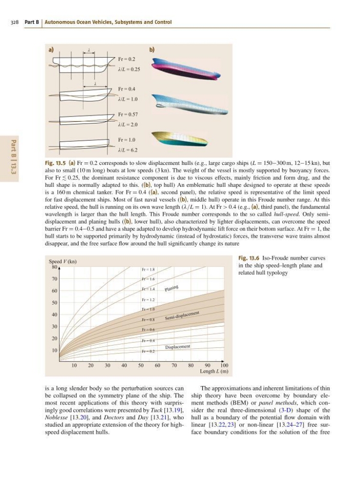
Fig. 13.6 Iso-Froude number curves
in the ship speed–length plane and
related hull typology
is a long slender body so the perturbation sources can
be collapsed on the symmetry plane of the ship. The
most recent applications of this theory with surprisingly good correlations were presented by Tuck [13.19],
Noblesse [13.20], and Doctors and Day [13.21], who
studied an appropriate extension of the theory for highspeed displacement hulls.
The approximations and inherent limitations of thin
ship theory have been overcome by boundary element methods (BEM) or panel methods, which consider the real three-dimensional (3-D) shape of the
hull as a boundary of the potential flow domain with
linear [13.22, 23] or non-linear [13.24–27] free surface boundary conditions for the solution of the free
328 Part B Autonomous Ocean Vehicles, Subsystems and Control
λ
λ
λ/L = 0.25
a)
b)
Fr = 0.2
λ/L = 1.0
Fr = 0.4
λ/L = 2.0
Fr = 0.57
λ/L = 6.2
Fr = 1.0
Fig. 13.5 (a) Fr D 0:2 corresponds to slow displacement hulls (e.g., large cargo ships (L D 150300 m, 1215 kn), but
also to small (10 m long) boats at low speeds (3 kn). The weight of the vessel is mostly supported by buoyancy forces.
For Fr . 0:25, the dominant resistance component is due to viscous effects, mainly friction and form drag, and the
hull shape is normally adapted to this. ((b), top hull) An emblematic hull shape designed to operate at these speeds
is a 160 m chemical tanker. For Fr D 0:4 ((a), second panel), the relative speed is representative of the limit speed
for fast displacement ships. Most of fast naval vessels ((b), middle hull) operate in this Froude number range. At this
relative speed, the hull is running on its own wave length (=L D 1). At Fr > 0:4 (e.g., (a), third panel), the fundamental
wavelength is larger than the hull length. This Froude number corresponds to the so called hull-speed. Only semidisplacement and planing hulls ((b), lower hull), also characterized by lighter displacements, can overcome the speed
barrier Fr D 0:40:5 and have a shape adapted to develop hydrodynamic lift force on their bottom surface. At Fr D 1, the
hull starts to be supported primarily by hydrodynamic (instead of hydrostatic) forces, the transverse wave trains almost
disappear, and the free surface flow around the hull significantly change its nature
10
20
30
40
50
60
Displac ement
Se mi -d isp lac em en t
P la n in g
Fr = 1.8
Fr = 1.6
Fr = 1.4
Fr = 1.2
Fr = 1.0
Fr = 0.8
Fr = 0.6
Fr = 0.4
Fr = 0.2
70
80
90
100
Speed V (kn)
Length L (m)
80
70
60
50
40
30
20
10
Fig. 13.6 Iso-Froude number curves
in the ship speed–length plane and
related hull typology
is a long slender body so the perturbation sources can
be collapsed on the symmetry plane of the ship. The
most recent applications of this theory with surprisingly good correlations were presented by Tuck [13.19],
Noblesse [13.20], and Doctors and Day [13.21], who
studied an appropriate extension of the theory for highspeed displacement hulls.
The approximations and inherent limitations of thin
ship theory have been overcome by boundary element methods (BEM) or panel methods, which consider the real three-dimensional (3-D) shape of the
hull as a boundary of the potential flow domain with
linear [13.22, 23] or non-linear [13.24–27] free surface boundary conditions for the solution of the free