

Part B | 12.1
302 Part B Autonomous Ocean Vehicles, Subsystems and Control
DU = Bw
Sawtooth glide path
Force
triangle
G li d e sl o p e
Horizontal plane
Wing
Speed
triangle
DU
Bu
=
D
L
w
u
D
B
+ B
– B
=
w
u
γ
α
α
w
U
τ
Γ
Specific energy consumption, E e =
Rate of working by
gravity, P g = Bw
Drag power, P e = DU
Flow circulation
Reaction torque
(pitching moment)
B
L
F
D
U
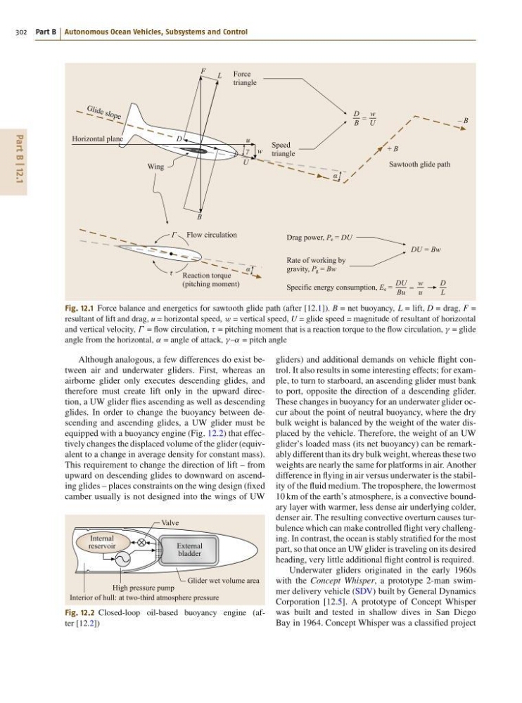
Fig. 12.1 Force balance and energetics for sawtooth glide path (after [12.1]). B = net buoyancy, L = lift, D = drag, F =
resultant of lift and drag, u = horizontal speed, w = vertical speed, U = glide speed = magnitude of resultant of horizontal
and vertical velocity, = flow circulation, = pitching moment that is a reaction torque to the flow circulation, = glide
angle from the horizontal, ˛ = angle of attack, –˛ = pitch angle
Although analogous, a few differences do exist between air and underwater gliders. First, whereas an
airborne glider only executes descending glides, and
therefore must create lift only in the upward direction, a UW glider flies ascending as well as descending
glides. In order to change the buoyancy between descending and ascending glides, a UW glider must be
equipped with a buoyancy engine (Fig. 12.2) that effectively changes the displaced volume of the glider (equivalent to a change in average density for constant mass).
This requirement to change the direction of lift – from
upward on descending glides to downward on ascending glides – places constraints on the wing design (fixed
camber usually is not designed into the wings of UW
Internal
reservoir
External
bladder
Valve
Glider wet volume area
High pressure pump
Interior of hull: at two-third atmosphere pressure
Fig. 12.2 Closed-loop oil-based buoyancy engine (after [12.2])
gliders) and additional demands on vehicle flight control. It also results in some interesting effects; for example, to turn to starboard, an ascending glider must bank
to port, opposite the direction of a descending glider.
These changes in buoyancy for an underwater glider occur about the point of neutral buoyancy, where the dry
bulk weight is balanced by the weight of the water displaced by the vehicle. Therefore, the weight of an UW
glider’s loaded mass (its net buoyancy) can be remarkably different than its dry bulk weight, whereas these two
weights are nearly the same for platforms in air. Another
difference in flying in air versus underwater is the stability of the fluid medium. The troposphere, the lowermost
10 km of the earth’s atmosphere, is a convective boundary layer with warmer, less dense air underlying colder,
denser air. The resulting convective overturn causes turbulence which can make controlled flight very challenging. In contrast, the ocean is stably stratified for the most
part, so that once an UW glider is traveling on its desired
heading, very little additional flight control is required.
Underwater gliders originated in the early 1960s
with the Concept Whisper, a prototype 2-man swimmer delivery vehicle (SDV) built by General Dynamics
Corporation [12.5]. A prototype of Concept Whisper
was built and tested in shallow dives in San Diego
Bay in 1964. Concept Whisper was a classified project
302 Part B Autonomous Ocean Vehicles, Subsystems and Control
DU = Bw
Sawtooth glide path
Force
triangle
G li d e sl o p e
Horizontal plane
Wing
Speed
triangle
DU
Bu
=
D
L
w
u
D
B
+ B
– B
=
w
u
γ
α
α
w
U
τ
Γ
Specific energy consumption, E e =
Rate of working by
gravity, P g = Bw
Drag power, P e = DU
Flow circulation
Reaction torque
(pitching moment)
B
L
F
D
U
Fig. 12.1 Force balance and energetics for sawtooth glide path (after [12.1]). B = net buoyancy, L = lift, D = drag, F =
resultant of lift and drag, u = horizontal speed, w = vertical speed, U = glide speed = magnitude of resultant of horizontal
and vertical velocity, = flow circulation, = pitching moment that is a reaction torque to the flow circulation, = glide
angle from the horizontal, ˛ = angle of attack, –˛ = pitch angle
Although analogous, a few differences do exist between air and underwater gliders. First, whereas an
airborne glider only executes descending glides, and
therefore must create lift only in the upward direction, a UW glider flies ascending as well as descending
glides. In order to change the buoyancy between descending and ascending glides, a UW glider must be
equipped with a buoyancy engine (Fig. 12.2) that effectively changes the displaced volume of the glider (equivalent to a change in average density for constant mass).
This requirement to change the direction of lift – from
upward on descending glides to downward on ascending glides – places constraints on the wing design (fixed
camber usually is not designed into the wings of UW
Internal
reservoir
External
bladder
Valve
Glider wet volume area
High pressure pump
Interior of hull: at two-third atmosphere pressure
Fig. 12.2 Closed-loop oil-based buoyancy engine (after [12.2])
gliders) and additional demands on vehicle flight control. It also results in some interesting effects; for example, to turn to starboard, an ascending glider must bank
to port, opposite the direction of a descending glider.
These changes in buoyancy for an underwater glider occur about the point of neutral buoyancy, where the dry
bulk weight is balanced by the weight of the water displaced by the vehicle. Therefore, the weight of an UW
glider’s loaded mass (its net buoyancy) can be remarkably different than its dry bulk weight, whereas these two
weights are nearly the same for platforms in air. Another
difference in flying in air versus underwater is the stability of the fluid medium. The troposphere, the lowermost
10 km of the earth’s atmosphere, is a convective boundary layer with warmer, less dense air underlying colder,
denser air. The resulting convective overturn causes turbulence which can make controlled flight very challenging. In contrast, the ocean is stably stratified for the most
part, so that once an UW glider is traveling on its desired
heading, very little additional flight control is required.
Underwater gliders originated in the early 1960s
with the Concept Whisper, a prototype 2-man swimmer delivery vehicle (SDV) built by General Dynamics
Corporation [12.5]. A prototype of Concept Whisper
was built and tested in shallow dives in San Diego
Bay in 1964. Concept Whisper was a classified project