

Highly Maneuverable Biorobotic Underwater Vehicles 11.3 Description of Biology-Inspired Vehicles of Emergent Maturity 289
Part B | 11.3
11.3 Description of Biology-Inspired Vehicles of Emergent Maturity
Tables 11.2 and 11.3 summarize the salient features of
the more mature bio-inspired and bio-mimicry vehicles,
respectively. Brief descriptions of the bio-inspired vehicles and sample results are presented in Figs. 11.3
through 11.6. Table 11.4 summarizes the salient features of the engineering controllers (i. e., PID gain,
adaptive, or cascading controllers) and olivo-cerebellar
controllers that were crucial to demonstration of the
low-speed maneuverability of the bio-inspired vehicles.
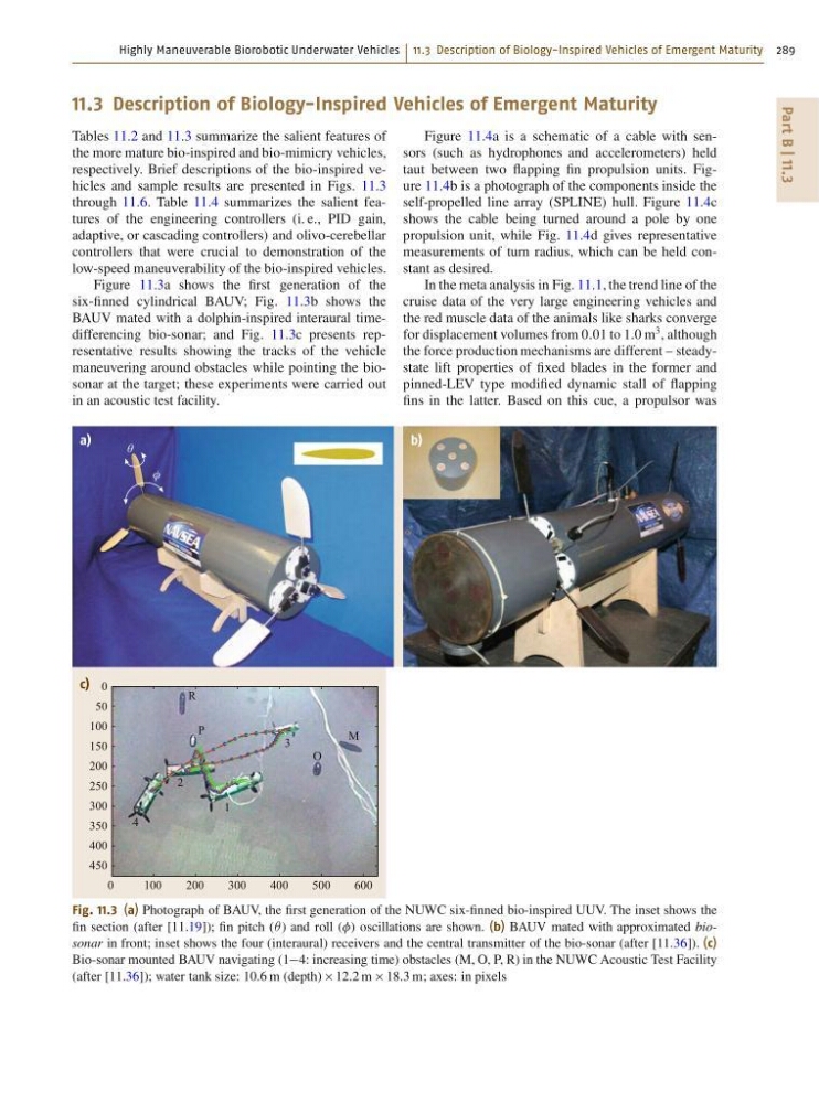
Figure 11.3a shows the first generation of the
six-finned cylindrical BAUV; Fig. 11.3b shows the
BAUV mated with a dolphin-inspired interaural timedifferencing bio-sonar; and Fig. 11.3c presents representative results showing the tracks of the vehicle
maneuvering around obstacles while pointing the biosonar at the target; these experiments were carried out
in an acoustic test facility.
0
100
200
300
400
500
600
R
P
2
1
3
4
M
O
c)
b)
a)
θ
φ
0
50
100
150
200
250
300
350
400
450
Fig. 11.3 (a) Photograph of BAUV, the first generation of the NUWC six-finned bio-inspired UUV. The inset shows the
fin section (after [11.19]); fin pitch (Â) and roll () oscillations are shown. (b) BAUV mated with approximated biosonar in front; inset shows the four (interaural) receivers and the central transmitter of the bio-sonar (after [11.36]). (c)
Bio-sonar mounted BAUV navigating (14: increasing time) obstacles (M, O, P, R) in the NUWC Acoustic Test Facility
(after [11.36]); water tank size: 10:6 m (depth) 12:2 m 18:3 m; axes: in pixels
Figure 11.4a is a schematic of a cable with sensors (such as hydrophones and accelerometers) held
taut between two flapping fin propulsion units. Figure 11.4b is a photograph of the components inside the
self-propelled line array (SPLINE) hull. Figure 11.4c
shows the cable being turned around a pole by one
propulsion unit, while Fig. 11.4d gives representative
measurements of turn radius, which can be held constant as desired.
In the meta analysis in Fig. 11.1, the trend line of the
cruise data of the very large engineering vehicles and
the red muscle data of the animals like sharks converge
for displacement volumes from 0:01 to 1:0 m
3 , although
the force production mechanisms are different – steadystate lift properties of fixed blades in the former and
pinned-LEV type modified dynamic stall of flapping
fins in the latter. Based on this cue, a propulsor was
Part B | 11.3
11.3 Description of Biology-Inspired Vehicles of Emergent Maturity
Tables 11.2 and 11.3 summarize the salient features of
the more mature bio-inspired and bio-mimicry vehicles,
respectively. Brief descriptions of the bio-inspired vehicles and sample results are presented in Figs. 11.3
through 11.6. Table 11.4 summarizes the salient features of the engineering controllers (i. e., PID gain,
adaptive, or cascading controllers) and olivo-cerebellar
controllers that were crucial to demonstration of the
low-speed maneuverability of the bio-inspired vehicles.
Figure 11.3a shows the first generation of the
six-finned cylindrical BAUV; Fig. 11.3b shows the
BAUV mated with a dolphin-inspired interaural timedifferencing bio-sonar; and Fig. 11.3c presents representative results showing the tracks of the vehicle
maneuvering around obstacles while pointing the biosonar at the target; these experiments were carried out
in an acoustic test facility.
0
100
200
300
400
500
600
R
P
2
1
3
4
M
O
c)
b)
a)
θ
φ
0
50
100
150
200
250
300
350
400
450
Fig. 11.3 (a) Photograph of BAUV, the first generation of the NUWC six-finned bio-inspired UUV. The inset shows the
fin section (after [11.19]); fin pitch (Â) and roll () oscillations are shown. (b) BAUV mated with approximated biosonar in front; inset shows the four (interaural) receivers and the central transmitter of the bio-sonar (after [11.36]). (c)
Bio-sonar mounted BAUV navigating (14: increasing time) obstacles (M, O, P, R) in the NUWC Acoustic Test Facility
(after [11.36]); water tank size: 10:6 m (depth) 12:2 m 18:3 m; axes: in pixels
Figure 11.4a is a schematic of a cable with sensors (such as hydrophones and accelerometers) held
taut between two flapping fin propulsion units. Figure 11.4b is a photograph of the components inside the
self-propelled line array (SPLINE) hull. Figure 11.4c
shows the cable being turned around a pole by one
propulsion unit, while Fig. 11.4d gives representative
measurements of turn radius, which can be held constant as desired.
In the meta analysis in Fig. 11.1, the trend line of the
cruise data of the very large engineering vehicles and
the red muscle data of the animals like sharks converge
for displacement volumes from 0:01 to 1:0 m
3 , although
the force production mechanisms are different – steadystate lift properties of fixed blades in the former and
pinned-LEV type modified dynamic stall of flapping
fins in the latter. Based on this cue, a propulsor was