

Highly Maneuverable Biorobotic Underwater Vehicles 11.1 Biorobotics 285
Part B | 11.1
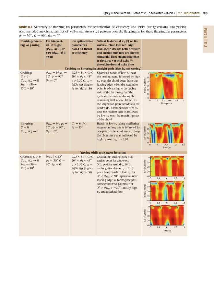
Table 11.1 Summary of flapping fin parameters for optimization of efficiency and thrust during cruising and yawing.
Also included are characteristics of wall-shear stress ( w ) patterns over the flapping fin for these flapping fin parameters:
0 D 30
ı , D 90
ı , Â t0 D 0
ı
Cruising, hovering, or yawing
Fin kinematics: straight
(Â Bias D 0), or
yaw (Â Bias ¤ 0)
swim
Fin optimization
parameters
based on thrust
or efficiency
Salient features of w .t/ on fin
surface (blue: low, red: high
wall-shear stress); both pressure
and suction surfaces are shown;
sinusoidal line: stagnation point
trajectory; vertical axis: %
chord, horizontal axis: time
Cruising or hovering in straight path (that is, not yawing)
Cruising:
U > 0
U wing =U t ! 0
Re c D .30
130/ 10 3
 Bias D 0 ı 0 D
30 ı D 90 ı
 t0 D 0 ı
0:25 Ä St Ä 0:40
20 ı Ä Â 0 Ä 45 ı
Á > 0:57 C x;Á D
fn.St; Â 0 / (higher
 0 for higher St)
Spanwise bands of low w near
the leading edge, followed by high
w over the chord away from the
leading edge when the stagnation
point is advancing to the facing
side of the fin during half the
cycle of oscillation; during the
remaining half of oscillation, as
the stagnation point recedes to the
other side, a thin band of high w
near the leading edge is followed
by low w over the remaining part
of the chord
0
1
0.8
0.6
0.4
0.2
Time/period
S/c (% of chord)
0
10
20
30
40
50
60
Hovering:
U D 0
U wing =U t ! 1
 Bias D 0 ı , 0 D
30 ı , D 90 ı ,
 t0 D 0 ı ,
C x D fn.f 2 /
 0 D 45 ı
Bands of low w along oscillating
stagnation line; this is followed by
one pair of a band of low w along
the chord per cycle, followed by
high w over s c =c > 0:05
0
1.6
1.2
0.8
0.4
Time (s)
S/c (% chord)
0
10
20
30
40
Yawing while cruising or hovering
Cruising: U > 0
U wing =U t ! 0
Re c D .30
130/ 10 3
j Bias j < 20 ı
0 D 30 ı D
90 ı Â t0 D 0 ı
0:25 Ä St Ä 0:40
20 ı Ä Â 0 Ä 45 ı
Á > 0:57 C x;Á D
fn.St; Â 0 / (higher
 0 for higher St)
Oscillating leading-edge stagnation point for zero (top,
0 ı ), positive (middle, 10 ı ),
and negative (bottom, 10 ı )
pitch bias; bands of low w for
0 ı < Â Bias < 20 ı : spanwise near
leading edge as for no yaw plus
some chordwise patterns; for
0 ı > Â Bias > 20 ı : mostly high
w and attached flow
0
1.6
1.2
0.8
0.4
S/c (% chord)
0
10
20
30
40
0
1.6
1.2
0.8
0.4
S/c (% chord)
0
10
20
30
40
0
1.6
1.2
0.8
0.4
Time (s)
S/c (% chord)
0
10
20
30
40
Part B | 11.1
Table 11.1 Summary of flapping fin parameters for optimization of efficiency and thrust during cruising and yawing.
Also included are characteristics of wall-shear stress ( w ) patterns over the flapping fin for these flapping fin parameters:
0 D 30
ı , D 90
ı , Â t0 D 0
ı
Cruising, hovering, or yawing
Fin kinematics: straight
(Â Bias D 0), or
yaw (Â Bias ¤ 0)
swim
Fin optimization
parameters
based on thrust
or efficiency
Salient features of w .t/ on fin
surface (blue: low, red: high
wall-shear stress); both pressure
and suction surfaces are shown;
sinusoidal line: stagnation point
trajectory; vertical axis: %
chord, horizontal axis: time
Cruising or hovering in straight path (that is, not yawing)
Cruising:
U > 0
U wing =U t ! 0
Re c D .30
130/ 10 3
 Bias D 0 ı 0 D
30 ı D 90 ı
 t0 D 0 ı
0:25 Ä St Ä 0:40
20 ı Ä Â 0 Ä 45 ı
Á > 0:57 C x;Á D
fn.St; Â 0 / (higher
 0 for higher St)
Spanwise bands of low w near
the leading edge, followed by high
w over the chord away from the
leading edge when the stagnation
point is advancing to the facing
side of the fin during half the
cycle of oscillation; during the
remaining half of oscillation, as
the stagnation point recedes to the
other side, a thin band of high w
near the leading edge is followed
by low w over the remaining part
of the chord
0
1
0.8
0.6
0.4
0.2
Time/period
S/c (% of chord)
0
10
20
30
40
50
60
Hovering:
U D 0
U wing =U t ! 1
 Bias D 0 ı , 0 D
30 ı , D 90 ı ,
 t0 D 0 ı ,
C x D fn.f 2 /
 0 D 45 ı
Bands of low w along oscillating
stagnation line; this is followed by
one pair of a band of low w along
the chord per cycle, followed by
high w over s c =c > 0:05
0
1.6
1.2
0.8
0.4
Time (s)
S/c (% chord)
0
10
20
30
40
Yawing while cruising or hovering
Cruising: U > 0
U wing =U t ! 0
Re c D .30
130/ 10 3
j Bias j < 20 ı
0 D 30 ı D
90 ı Â t0 D 0 ı
0:25 Ä St Ä 0:40
20 ı Ä Â 0 Ä 45 ı
Á > 0:57 C x;Á D
fn.St; Â 0 / (higher
 0 for higher St)
Oscillating leading-edge stagnation point for zero (top,
0 ı ), positive (middle, 10 ı ),
and negative (bottom, 10 ı )
pitch bias; bands of low w for
0 ı < Â Bias < 20 ı : spanwise near
leading edge as for no yaw plus
some chordwise patterns; for
0 ı > Â Bias > 20 ı : mostly high
w and attached flow
0
1.6
1.2
0.8
0.4
S/c (% chord)
0
10
20
30
40
0
1.6
1.2
0.8
0.4
S/c (% chord)
0
10
20
30
40
0
1.6
1.2
0.8
0.4
Time (s)
S/c (% chord)
0
10
20
30
40