

Part B | 11.1
284 Part B Autonomous Ocean Vehicles, Subsystems and Control
r
r
s
s, p
p
a)
b)
d)
c)
e)
α g
α
U t
U t
U t
U wing (t)
U
0
0.2 0.4 0.6
C x, wing
C x, wing
0.8
1
1.2 1.4 1.6
f) θ 0, R avg (deg)
St
80
70
60
50
40
30
20
10
0
1.4
1.2
1
0.8
0.6
0.4
0.2
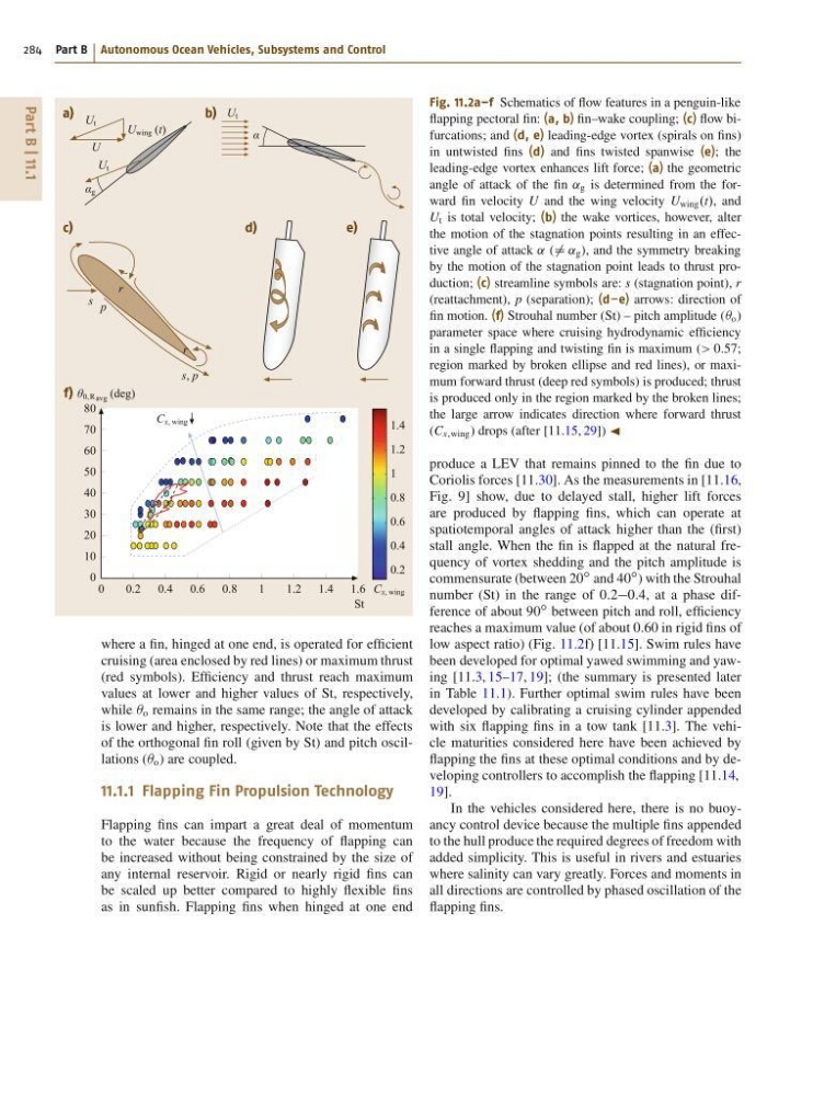
where a fin, hinged at one end, is operated for efficient
cruising (area enclosed by red lines) or maximum thrust
(red symbols). Efficiency and thrust reach maximum
values at lower and higher values of St, respectively,
while  o remains in the same range; the angle of attack
is lower and higher, respectively. Note that the effects
of the orthogonal fin roll (given by St) and pitch oscillations (Â o ) are coupled.
11.1.1 Flapping Fin Propulsion Technology
Flapping fins can impart a great deal of momentum
to the water because the frequency of flapping can
be increased without being constrained by the size of
any internal reservoir. Rigid or nearly rigid fins can
be scaled up better compared to highly flexible fins
as in sunfish. Flapping fins when hinged at one end
Fig. 11.2a–f Schematics of flow features in a penguin-like
flapping pectoral fin: (a, b) fin–wake coupling; (c) flow bifurcations; and (d, e) leading-edge vortex (spirals on fins)
in untwisted fins (d) and fins twisted spanwise (e); the
leading-edge vortex enhances lift force; (a) the geometric
angle of attack of the fin ˛ g is determined from the forward fin velocity U and the wing velocity U wing .t/, and
U t is total velocity; (b) the wake vortices, however, alter
the motion of the stagnation points resulting in an effective angle of attack ˛ (¤ ˛ g ), and the symmetry breaking
by the motion of the stagnation point leads to thrust production; (c) streamline symbols are: s (stagnation point), r
(reattachment), p (separation); (d–e) arrows: direction of
fin motion. (f) Strouhal number (St) – pitch amplitude (Â o )
parameter space where cruising hydrodynamic efficiency
in a single flapping and twisting fin is maximum (> 0:57;
region marked by broken ellipse and red lines), or maximum forward thrust (deep red symbols) is produced; thrust
is produced only in the region marked by the broken lines;
the large arrow indicates direction where forward thrust
(C x;wing ) drops (after [11.15, 29]) J
produce a LEV that remains pinned to the fin due to
Coriolis forces [11.30]. As the measurements in [11.16,
Fig. 9] show, due to delayed stall, higher lift forces
are produced by flapping fins, which can operate at
spatiotemporal angles of attack higher than the (first)
stall angle. When the fin is flapped at the natural frequency of vortex shedding and the pitch amplitude is
commensurate (between 20
ı and 40
ı ) with the Strouhal
number (St) in the range of 0:20:4, at a phase difference of about 90
ı between pitch and roll, efficiency
reaches a maximum value (of about 0:60 in rigid fins of
low aspect ratio) (Fig. 11.2f) [11.15]. Swim rules have
been developed for optimal yawed swimming and yawing [11.3, 15–17, 19]; (the summary is presented later
in Table 11.1). Further optimal swim rules have been
developed by calibrating a cruising cylinder appended
with six flapping fins in a tow tank [11.3]. The vehicle maturities considered here have been achieved by
flapping the fins at these optimal conditions and by developing controllers to accomplish the flapping [11.14,
19].
In the vehicles considered here, there is no buoyancy control device because the multiple fins appended
to the hull produce the required degrees of freedom with
added simplicity. This is useful in rivers and estuaries
where salinity can vary greatly. Forces and moments in
all directions are controlled by phased oscillation of the
flapping fins.
284 Part B Autonomous Ocean Vehicles, Subsystems and Control
r
r
s
s, p
p
a)
b)
d)
c)
e)
α g
α
U t
U t
U t
U wing (t)
U
0
0.2 0.4 0.6
C x, wing
C x, wing
0.8
1
1.2 1.4 1.6
f) θ 0, R avg (deg)
St
80
70
60
50
40
30
20
10
0
1.4
1.2
1
0.8
0.6
0.4
0.2
where a fin, hinged at one end, is operated for efficient
cruising (area enclosed by red lines) or maximum thrust
(red symbols). Efficiency and thrust reach maximum
values at lower and higher values of St, respectively,
while  o remains in the same range; the angle of attack
is lower and higher, respectively. Note that the effects
of the orthogonal fin roll (given by St) and pitch oscillations (Â o ) are coupled.
11.1.1 Flapping Fin Propulsion Technology
Flapping fins can impart a great deal of momentum
to the water because the frequency of flapping can
be increased without being constrained by the size of
any internal reservoir. Rigid or nearly rigid fins can
be scaled up better compared to highly flexible fins
as in sunfish. Flapping fins when hinged at one end
Fig. 11.2a–f Schematics of flow features in a penguin-like
flapping pectoral fin: (a, b) fin–wake coupling; (c) flow bifurcations; and (d, e) leading-edge vortex (spirals on fins)
in untwisted fins (d) and fins twisted spanwise (e); the
leading-edge vortex enhances lift force; (a) the geometric
angle of attack of the fin ˛ g is determined from the forward fin velocity U and the wing velocity U wing .t/, and
U t is total velocity; (b) the wake vortices, however, alter
the motion of the stagnation points resulting in an effective angle of attack ˛ (¤ ˛ g ), and the symmetry breaking
by the motion of the stagnation point leads to thrust production; (c) streamline symbols are: s (stagnation point), r
(reattachment), p (separation); (d–e) arrows: direction of
fin motion. (f) Strouhal number (St) – pitch amplitude (Â o )
parameter space where cruising hydrodynamic efficiency
in a single flapping and twisting fin is maximum (> 0:57;
region marked by broken ellipse and red lines), or maximum forward thrust (deep red symbols) is produced; thrust
is produced only in the region marked by the broken lines;
the large arrow indicates direction where forward thrust
(C x;wing ) drops (after [11.15, 29]) J
produce a LEV that remains pinned to the fin due to
Coriolis forces [11.30]. As the measurements in [11.16,
Fig. 9] show, due to delayed stall, higher lift forces
are produced by flapping fins, which can operate at
spatiotemporal angles of attack higher than the (first)
stall angle. When the fin is flapped at the natural frequency of vortex shedding and the pitch amplitude is
commensurate (between 20
ı and 40
ı ) with the Strouhal
number (St) in the range of 0:20:4, at a phase difference of about 90
ı between pitch and roll, efficiency
reaches a maximum value (of about 0:60 in rigid fins of
low aspect ratio) (Fig. 11.2f) [11.15]. Swim rules have
been developed for optimal yawed swimming and yawing [11.3, 15–17, 19]; (the summary is presented later
in Table 11.1). Further optimal swim rules have been
developed by calibrating a cruising cylinder appended
with six flapping fins in a tow tank [11.3]. The vehicle maturities considered here have been achieved by
flapping the fins at these optimal conditions and by developing controllers to accomplish the flapping [11.14,
19].
In the vehicles considered here, there is no buoyancy control device because the multiple fins appended
to the hull produce the required degrees of freedom with
added simplicity. This is useful in rivers and estuaries
where salinity can vary greatly. Forces and moments in
all directions are controlled by phased oscillation of the
flapping fins.