

Control Theory and Applications 10.3 SISO System Controls 259
Part A | 10.3
50
300
Zero-order
hold
PID
controller
Saturation
Gain
Gain 1
To workspace 1
W
W |W |
Step
s
1
U
s
1
PID(s)
W1
0.2 u abs (u)
u
To workspace
To workspace 2
Clock
ω
t
0.04 u abs (u)
U |U |
20 u abs (u)
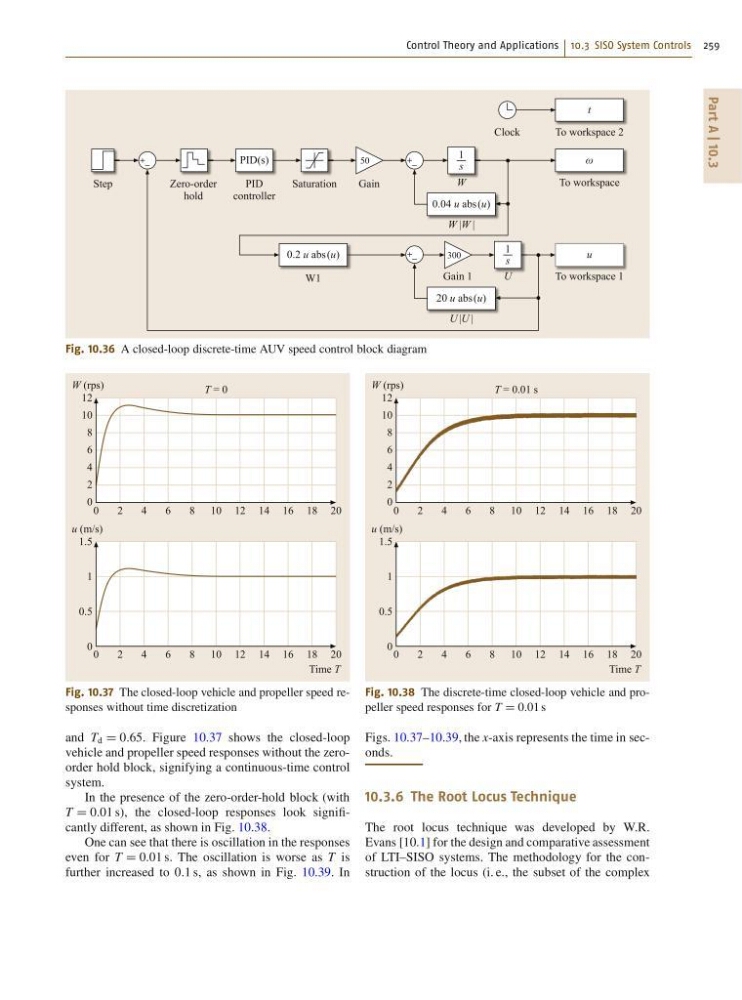
Fig. 10.36 A closed-loop discrete-time AUV speed control block diagram
0
2
4
6
8 10
T = 0
12 14 16 18 20
W (rps)
Time T
12
10
8
6
4
2
0
0
2
4
6
8 10 12 14 16 18 20
u (m/s)
1.5
1
0.5
0
Fig. 10.37 The closed-loop vehicle and propeller speed responses without time discretization
and T d D 0:65. Figure 10.37 shows the closed-loop
vehicle and propeller speed responses without the zeroorder hold block, signifying a continuous-time control
system.
In the presence of the zero-order-hold block (with
T D 0:01 s), the closed-loop responses look significantly different, as shown in Fig. 10.38.
One can see that there is oscillation in the responses
even for T D 0:01 s. The oscillation is worse as T is
further increased to 0:1 s, as shown in Fig. 10.39. In
0
2
4
6
8 10
T = 0.01 s
12 14 16 18 20
W (rps)
Time T
12
10
8
6
4
2
0
0
2
4
6
8 10 12 14 16 18 20
u (m/s)
1.5
1
0.5
0
Fig. 10.38 The discrete-time closed-loop vehicle and propeller speed responses for T D 0:01 s
Figs. 10.37–10.39, the x-axis represents the time in seconds.
10.3.6 The Root Locus Technique
The root locus technique was developed by W.R.
Evans [10.1] for the design and comparative assessment
of LTI–SISO systems. The methodology for the construction of the locus (i. e., the subset of the complex
Part A | 10.3
50
300
Zero-order
hold
PID
controller
Saturation
Gain
Gain 1
To workspace 1
W
W |W |
Step
s
1
U
s
1
PID(s)
W1
0.2 u abs (u)
u
To workspace
To workspace 2
Clock
ω
t
0.04 u abs (u)
U |U |
20 u abs (u)
Fig. 10.36 A closed-loop discrete-time AUV speed control block diagram
0
2
4
6
8 10
T = 0
12 14 16 18 20
W (rps)
Time T
12
10
8
6
4
2
0
0
2
4
6
8 10 12 14 16 18 20
u (m/s)
1.5
1
0.5
0
Fig. 10.37 The closed-loop vehicle and propeller speed responses without time discretization
and T d D 0:65. Figure 10.37 shows the closed-loop
vehicle and propeller speed responses without the zeroorder hold block, signifying a continuous-time control
system.
In the presence of the zero-order-hold block (with
T D 0:01 s), the closed-loop responses look significantly different, as shown in Fig. 10.38.
One can see that there is oscillation in the responses
even for T D 0:01 s. The oscillation is worse as T is
further increased to 0:1 s, as shown in Fig. 10.39. In
0
2
4
6
8 10
T = 0.01 s
12 14 16 18 20
W (rps)
Time T
12
10
8
6
4
2
0
0
2
4
6
8 10 12 14 16 18 20
u (m/s)
1.5
1
0.5
0
Fig. 10.38 The discrete-time closed-loop vehicle and propeller speed responses for T D 0:01 s
Figs. 10.37–10.39, the x-axis represents the time in seconds.
10.3.6 The Root Locus Technique
The root locus technique was developed by W.R.
Evans [10.1] for the design and comparative assessment
of LTI–SISO systems. The methodology for the construction of the locus (i. e., the subset of the complex