

Control Theory and Applications 10.3 SISO System Controls 251
Part A | 10.3
Integral
gain
Proportional
gain
Integrator
Differential
gain
Derivative
Setpoint
value
Tracking
error
e
Control
action
u
Actual
value
y
Overall
gain
du/dt
K
K p
K d
K i
1
s
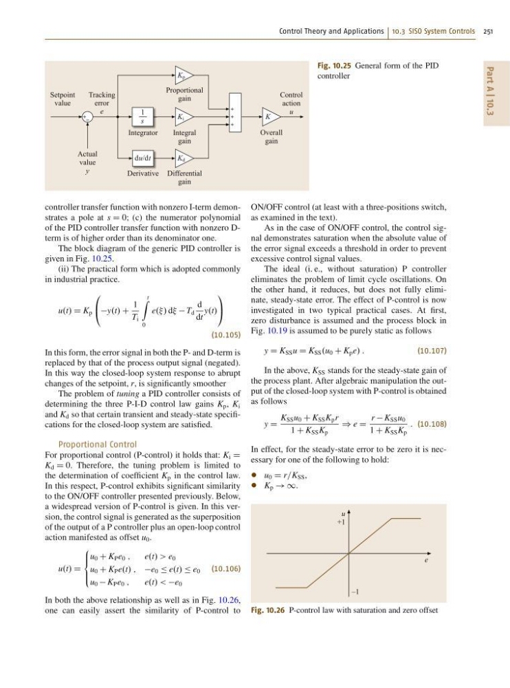
Fig. 10.25 General form of the PID
controller
controller transfer function with nonzero I-term demonstrates a pole at s D 0; (c) the numerator polynomial
of the PID controller transfer function with nonzero Dterm is of higher order than its denominator one.
The block diagram of the generic PID controller is
given in Fig. 10.25.
(ii) The practical form which is adopted commonly
in industrial practice.
u.t/ D K p
0
@ y.t/ C
1
T i
t
Z
0
e../ d T d
d
dt
y.t/
1
A
(10.105)
In this form, the error signal in both the P- and D-term is
replaced by that of the process output signal (negated).
In this way the closed-loop system response to abrupt
changes of the setpoint, r, is significantly smoother
The problem of tuning a PID controller consists of
determining the three P-I-D control law gains K p , K i
and K d so that certain transient and steady-state specifications for the closed-loop system are satisfied.
Proportional Control
For proportional control (P-control) it holds that: K i D
K d D 0. Therefore, the tuning problem is limited to
the determination of coefficient K p in the control law.
In this respect, P-control exhibits significant similarity
to the ON/OFF controller presented previously. Below,
a widespread version of P-control is given. In this version, the control signal is generated as the superposition
of the output of a P controller plus an open-loop control
action manifested as offset u 0 .
u.t/ D
8
ˆ <
ˆ :
u 0 C K P e 0 ;
e.t/ > e 0
u 0 C K P e.t/ ; e 0 Ä e.t/ Ä e 0
u 0 K P e 0 ;
e.t/ < e 0
(10.106)
In both the above relationship as well as in Fig. 10.26,
one can easily assert the similarity of P-control to
ON/OFF control (at least with a three-positions switch,
as examined in the text).
As in the case of ON/OFF control, the control signal demonstrates saturation when the absolute value of
the error signal exceeds a threshold in order to prevent
excessive control signal values.
The ideal (i. e., without saturation) P controller
eliminates the problem of limit cycle oscillations. On
the other hand, it reduces, but does not fully eliminate, steady-state error. The effect of P-control is now
investigated in two typical practical cases. At first,
zero disturbance is assumed and the process block in
Fig. 10.19 is assumed to be purely static as follows
y D K SS u D K SS .u 0 C K p e/ :
(10.107)
In the above, K SS stands for the steady-state gain of
the process plant. After algebraic manipulation the output of the closed-loop system with P-control is obtained
as follows
y D
K SS u 0 C K SS K p r
1 C K SS K p
) e D
r K SS u 0
1 C K SS K p
: (10.108)
In effect, for the steady-state error to be zero it is necessary for one of the following to hold:
u 0 D r=K SS ,
K p ! 1.
u
+1
–1
e
Fig. 10.26 P-control law with saturation and zero offset
Part A | 10.3
Integral
gain
Proportional
gain
Integrator
Differential
gain
Derivative
Setpoint
value
Tracking
error
e
Control
action
u
Actual
value
y
Overall
gain
du/dt
K
K p
K d
K i
1
s
Fig. 10.25 General form of the PID
controller
controller transfer function with nonzero I-term demonstrates a pole at s D 0; (c) the numerator polynomial
of the PID controller transfer function with nonzero Dterm is of higher order than its denominator one.
The block diagram of the generic PID controller is
given in Fig. 10.25.
(ii) The practical form which is adopted commonly
in industrial practice.
u.t/ D K p
0
@ y.t/ C
1
T i
t
Z
0
e../ d T d
d
dt
y.t/
1
A
(10.105)
In this form, the error signal in both the P- and D-term is
replaced by that of the process output signal (negated).
In this way the closed-loop system response to abrupt
changes of the setpoint, r, is significantly smoother
The problem of tuning a PID controller consists of
determining the three P-I-D control law gains K p , K i
and K d so that certain transient and steady-state specifications for the closed-loop system are satisfied.
Proportional Control
For proportional control (P-control) it holds that: K i D
K d D 0. Therefore, the tuning problem is limited to
the determination of coefficient K p in the control law.
In this respect, P-control exhibits significant similarity
to the ON/OFF controller presented previously. Below,
a widespread version of P-control is given. In this version, the control signal is generated as the superposition
of the output of a P controller plus an open-loop control
action manifested as offset u 0 .
u.t/ D
8
ˆ <
ˆ :
u 0 C K P e 0 ;
e.t/ > e 0
u 0 C K P e.t/ ; e 0 Ä e.t/ Ä e 0
u 0 K P e 0 ;
e.t/ < e 0
(10.106)
In both the above relationship as well as in Fig. 10.26,
one can easily assert the similarity of P-control to
ON/OFF control (at least with a three-positions switch,
as examined in the text).
As in the case of ON/OFF control, the control signal demonstrates saturation when the absolute value of
the error signal exceeds a threshold in order to prevent
excessive control signal values.
The ideal (i. e., without saturation) P controller
eliminates the problem of limit cycle oscillations. On
the other hand, it reduces, but does not fully eliminate, steady-state error. The effect of P-control is now
investigated in two typical practical cases. At first,
zero disturbance is assumed and the process block in
Fig. 10.19 is assumed to be purely static as follows
y D K SS u D K SS .u 0 C K p e/ :
(10.107)
In the above, K SS stands for the steady-state gain of
the process plant. After algebraic manipulation the output of the closed-loop system with P-control is obtained
as follows
y D
K SS u 0 C K SS K p r
1 C K SS K p
) e D
r K SS u 0
1 C K SS K p
: (10.108)
In effect, for the steady-state error to be zero it is necessary for one of the following to hold:
u 0 D r=K SS ,
K p ! 1.
u
+1
–1
e
Fig. 10.26 P-control law with saturation and zero offset