

Digital Signal Processing 9.2 Digital Filters 209
Part A | 9.2
z
–1
FIR
filter
D' (z)
x (n)
y (n)
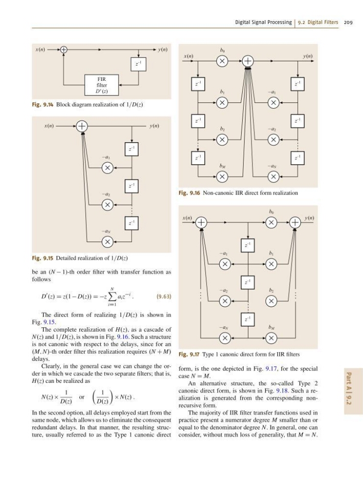
Fig. 9.14 Block diagram realization of 1=D.z/
x (n)
y (n)
z
–1
z
–1
z
–1
– a 2
– a 1
– a N
Fig. 9.15 Detailed realization of 1=D.z/
be an (N 1)-th order filter with transfer function as
follows
D
0
.z/ D z.1 D.z// D Dz
N
X
iD1
a i z
i
:
(9.63)
The direct form of realizing 1=D.z/ is shown in
Fig. 9.15.
The complete realization of H.z/, as a cascade of
N.z/ and 1=D.z/, is shown in Fig. 9.16. Such a structure
is not canonic with respect to the delays, since for an
.M; N/-th order filter this realization requires .N C M/
delays.
Clearly, in the general case we can change the order in which we cascade the two separate filters; that is,
H.z/ can be realized as
N.z/
1
D.z/
or
 1
D.z/
Ã
N.z/ :
In the second option, all delays employed start from the
same node, which allows us to eliminate the consequent
redundant delays. In that manner, the resulting structure, usually referred to as the Type 1 canonic direct
x (n)
y (n)
z
–1
z
–1
z
–1
z
–1
z
–1
z
–1
– a 2
– a 1
– a N
b 2
b 1
b 0
b M
Fig. 9.16 Non-canonic IIR direct form realization
x (n)
y (n)
z
–1
z
–1
z
–1
– a 2
– a 1
– a N
b 2
b 1
b 0
b M
Fig. 9.17 Type 1 canonic direct form for IIR filters
form, is the one depicted in Fig. 9.17, for the special
case N D M.
An alternative structure, the so-called Type 2
canonic direct form, is shown in Fig. 9.18. Such a realization is generated from the corresponding nonrecursive form.
The majority of IIR filter transfer functions used in
practice present a numerator degree M smaller than or
equal to the denominator degree N. In general, one can
consider, without much loss of generality, that M D N.
Part A | 9.2
z
–1
FIR
filter
D' (z)
x (n)
y (n)
Fig. 9.14 Block diagram realization of 1=D.z/
x (n)
y (n)
z
–1
z
–1
z
–1
– a 2
– a 1
– a N
Fig. 9.15 Detailed realization of 1=D.z/
be an (N 1)-th order filter with transfer function as
follows
D
0
.z/ D z.1 D.z// D Dz
N
X
iD1
a i z
i
:
(9.63)
The direct form of realizing 1=D.z/ is shown in
Fig. 9.15.
The complete realization of H.z/, as a cascade of
N.z/ and 1=D.z/, is shown in Fig. 9.16. Such a structure
is not canonic with respect to the delays, since for an
.M; N/-th order filter this realization requires .N C M/
delays.
Clearly, in the general case we can change the order in which we cascade the two separate filters; that is,
H.z/ can be realized as
N.z/
1
D.z/
or
 1
D.z/
Ã
N.z/ :
In the second option, all delays employed start from the
same node, which allows us to eliminate the consequent
redundant delays. In that manner, the resulting structure, usually referred to as the Type 1 canonic direct
x (n)
y (n)
z
–1
z
–1
z
–1
z
–1
z
–1
z
–1
– a 2
– a 1
– a N
b 2
b 1
b 0
b M
Fig. 9.16 Non-canonic IIR direct form realization
x (n)
y (n)
z
–1
z
–1
z
–1
– a 2
– a 1
– a N
b 2
b 1
b 0
b M
Fig. 9.17 Type 1 canonic direct form for IIR filters
form, is the one depicted in Fig. 9.17, for the special
case N D M.
An alternative structure, the so-called Type 2
canonic direct form, is shown in Fig. 9.18. Such a realization is generated from the corresponding nonrecursive form.
The majority of IIR filter transfer functions used in
practice present a numerator degree M smaller than or
equal to the denominator degree N. In general, one can
consider, without much loss of generality, that M D N.