

Digital Signal Processing 9.1 Discrete-Time Systems 201
Part A | 9.1
t
x (t)
Fig. 9.5 Original continuous-time signal (continuous line)
and reconstructed version using a non-brick filter (dashed
line)
9.1.3 Analog Signal Reconstruction
Using a Discrete-Time Signal
The simplest process to generate a continuous-time signal, x.t/, from a discretized sequence (discrete-time
signal) x.n/ is to employ the zero-order hold (ZOH) network. This system holds the output constant and equal
to the one applied to its input for an entire sampling period T s . In effect, the output of ZOH when driven by
a discretized signal is given in the Fig. 9.5.
The mathematical description of a ZOH system is
achieved through the following impulse response and
transfer function in the complex frequency domain of
variable s
h ZOH .t/ D u step .t/ u step .t T s /
, H ZOH .s/ D
1 e
sTs
s
:
(9.19)
To better understand the action of the ZOH system, its
transfer function in the circular frequency domain !
(Fourier transform) is given below, as well
H ZOH .!/ D
1 e
i!Ts
i!
D T s e
i!Ts=2 sin.!T s =2/
.!T s =2/
D
e
i f =fs
f s
sinc.f =f s / :
(9.20)
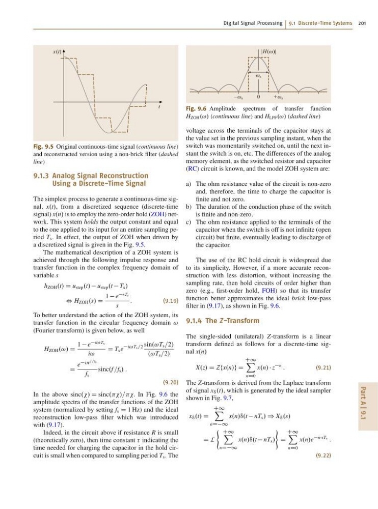
In the above sinc../ D sinc.../===. In Fig. 9.6 the
amplitude spectra of the transfer functions of the ZOH
system (normalized by setting f s D 1 Hz) and the ideal
reconstruction low-pass filter which was introduced
with (9.17).
Indeed, in the circuit above if resistance R is small
(theoretically zero), then time constant indicating the
time needed for charging the capacitor in the hold circuit is small when compared to sampling period T s . The
0
ω s
– ω s
+ω s
|H (ω)|
Fig. 9.6 Amplitude spectrum of transfer function
H ZOH .!/ (continuous line) and H LPF .!/ (dashed line)
voltage across the terminals of the capacitor stays at
the value set in the previous sampling instant, when the
switch was momentarily switched on, until the next instant the switch is on, etc. The differences of the analog
memory element, as the switched resistor and capacitor
(RC) circuit is known, and the model ZOH system are:
a) The ohm resistance value of the circuit is non-zero
and, therefore, the time to charge the capacitor is
finite and not zero.
b) The duration of the conduction phase of the switch
is finite and non-zero.
c) The ohm resistance applied to the terminals of the
capacitor when the switch is off is not infinite (open
circuit) but finite, eventually leading to discharge of
the capacitor.
The use of the RC hold circuit is widespread due
to its simplicity. However, if a more accurate reconstruction with less distortion, without increasing the
sampling rate, then hold circuits of order higher than
zero (e.g., first-order hold, FOH) so that its transfer
function better approximates the ideal brick low-pass
filter in (9.17), as shown in Fig. 9.6.
9.1.4 The Z-Transform
The single-sided (unilateral) Z-transform is a linear
transform defined as follows for a discrete-time signal x.n/
X.z/ D Zfx.n/g D
C1 X
nD0
x.n/ z
n
:
(9.21)
The Z-transform is derived from the Laplace transform
of signal x • .t/, which is generated by the ideal sampler
shown in Fig. 9.7,
x • .t/ D
C1 X
nDD1
x.n/•.t nT s / ) X • .s/
D L
( C1 X
nDD1
x.n/•.t nT s /
)
D
C1 X
nD0
x.n/e
nsTs
:
(9.22)
Part A | 9.1
t
x (t)
Fig. 9.5 Original continuous-time signal (continuous line)
and reconstructed version using a non-brick filter (dashed
line)
9.1.3 Analog Signal Reconstruction
Using a Discrete-Time Signal
The simplest process to generate a continuous-time signal, x.t/, from a discretized sequence (discrete-time
signal) x.n/ is to employ the zero-order hold (ZOH) network. This system holds the output constant and equal
to the one applied to its input for an entire sampling period T s . In effect, the output of ZOH when driven by
a discretized signal is given in the Fig. 9.5.
The mathematical description of a ZOH system is
achieved through the following impulse response and
transfer function in the complex frequency domain of
variable s
h ZOH .t/ D u step .t/ u step .t T s /
, H ZOH .s/ D
1 e
sTs
s
:
(9.19)
To better understand the action of the ZOH system, its
transfer function in the circular frequency domain !
(Fourier transform) is given below, as well
H ZOH .!/ D
1 e
i!Ts
i!
D T s e
i!Ts=2 sin.!T s =2/
.!T s =2/
D
e
i f =fs
f s
sinc.f =f s / :
(9.20)
In the above sinc../ D sinc.../===. In Fig. 9.6 the
amplitude spectra of the transfer functions of the ZOH
system (normalized by setting f s D 1 Hz) and the ideal
reconstruction low-pass filter which was introduced
with (9.17).
Indeed, in the circuit above if resistance R is small
(theoretically zero), then time constant indicating the
time needed for charging the capacitor in the hold circuit is small when compared to sampling period T s . The
0
ω s
– ω s
+ω s
|H (ω)|
Fig. 9.6 Amplitude spectrum of transfer function
H ZOH .!/ (continuous line) and H LPF .!/ (dashed line)
voltage across the terminals of the capacitor stays at
the value set in the previous sampling instant, when the
switch was momentarily switched on, until the next instant the switch is on, etc. The differences of the analog
memory element, as the switched resistor and capacitor
(RC) circuit is known, and the model ZOH system are:
a) The ohm resistance value of the circuit is non-zero
and, therefore, the time to charge the capacitor is
finite and not zero.
b) The duration of the conduction phase of the switch
is finite and non-zero.
c) The ohm resistance applied to the terminals of the
capacitor when the switch is off is not infinite (open
circuit) but finite, eventually leading to discharge of
the capacitor.
The use of the RC hold circuit is widespread due
to its simplicity. However, if a more accurate reconstruction with less distortion, without increasing the
sampling rate, then hold circuits of order higher than
zero (e.g., first-order hold, FOH) so that its transfer
function better approximates the ideal brick low-pass
filter in (9.17), as shown in Fig. 9.6.
9.1.4 The Z-Transform
The single-sided (unilateral) Z-transform is a linear
transform defined as follows for a discrete-time signal x.n/
X.z/ D Zfx.n/g D
C1 X
nD0
x.n/ z
n
:
(9.21)
The Z-transform is derived from the Laplace transform
of signal x • .t/, which is generated by the ideal sampler
shown in Fig. 9.7,
x • .t/ D
C1 X
nDD1
x.n/•.t nT s / ) X • .s/
D L
( C1 X
nDD1
x.n/•.t nT s /
)
D
C1 X
nD0
x.n/e
nsTs
:
(9.22)