

Part A | 6.3
114 Part A Fundamentals
Table 6.2 Typical steel properties
Composition [%]
Mechanical Properties
Steel
type
Description
C
Mn
S max P max Si
Cu
Ni
Cr
Fsy
[ksi]
Fsy
[MPa]
Fult
[ksi]
Fult
[MPa]
Carbon
steel
A36
General
purpose
structural
0:26
< 1:65
< 0:05 < 0:04 < 0:6
< 0:6
36
250
5880 400550
HSLA
A992
Ditto
0:23
0:51:5
0.045 0.035 0:4
0:6
0:45 < 0:35 5065 340450 65
450
HSLA
A588
Structural
weathering steel
0:150:2 0:751:35 0:05
0:04
0:150:4 0:20:5 < 0:5 0:37 4250 290350 6370 435480
Fsy D yield strength; Fult D ultimate strength; HSLA D high strength low alloy; Conversion: 1 MPa D 0:145 ksi (after [6.18])
ity transmission towers, and industrial and commercial
buildings. Mostly these are constructed from mild or
low alloy structural steels. Compared to more specialized steels, they are relatively cost-effective and readily
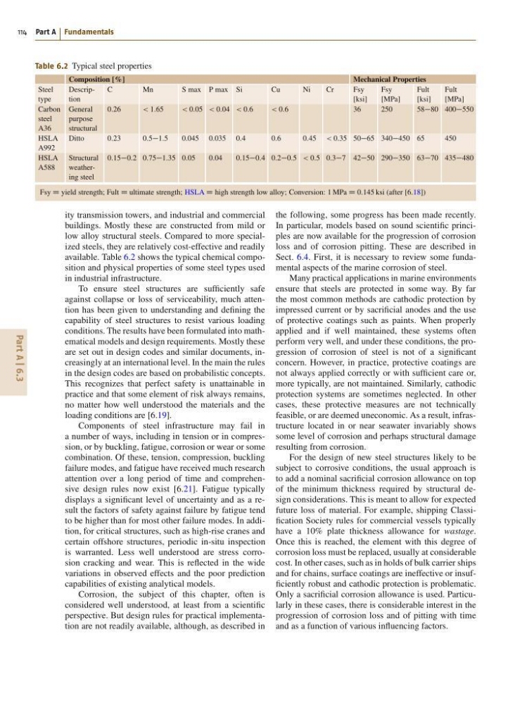
available. Table 6.2 shows the typical chemical composition and physical properties of some steel types used
in industrial infrastructure.
To ensure steel structures are sufficiently safe
against collapse or loss of serviceability, much attention has been given to understanding and defining the
capability of steel structures to resist various loading
conditions. The results have been formulated into mathematical models and design requirements. Mostly these
are set out in design codes and similar documents, increasingly at an international level. In the main the rules
in the design codes are based on probabilistic concepts.
This recognizes that perfect safety is unattainable in
practice and that some element of risk always remains,
no matter how well understood the materials and the
loading conditions are [6.19].
Components of steel infrastructure may fail in
a number of ways, including in tension or in compression, or by buckling, fatigue, corrosion or wear or some
combination. Of these, tension, compression, buckling
failure modes, and fatigue have received much research
attention over a long period of time and comprehensive design rules now exist [6.21]. Fatigue typically
displays a significant level of uncertainty and as a result the factors of safety against failure by fatigue tend
to be higher than for most other failure modes. In addition, for critical structures, such as high-rise cranes and
certain offshore structures, periodic in-situ inspection
is warranted. Less well understood are stress corrosion cracking and wear. This is reflected in the wide
variations in observed effects and the poor prediction
capabilities of existing analytical models.
Corrosion, the subject of this chapter, often is
considered well understood, at least from a scientific
perspective. But design rules for practical implementation are not readily available, although, as described in
the following, some progress has been made recently.
In particular, models based on sound scientific principles are now available for the progression of corrosion
loss and of corrosion pitting. These are described in
Sect. 6.4. First, it is necessary to review some fundamental aspects of the marine corrosion of steel.
Many practical applications in marine environments
ensure that steels are protected in some way. By far
the most common methods are cathodic protection by
impressed current or by sacrificial anodes and the use
of protective coatings such as paints. When properly
applied and if well maintained, these systems often
perform very well, and under these conditions, the progression of corrosion of steel is not of a significant
concern. However, in practice, protective coatings are
not always applied correctly or with sufficient care or,
more typically, are not maintained. Similarly, cathodic
protection systems are sometimes neglected. In other
cases, these protective measures are not technically
feasible, or are deemed uneconomic. As a result, infrastructure located in or near seawater invariably shows
some level of corrosion and perhaps structural damage
resulting from corrosion.
For the design of new steel structures likely to be
subject to corrosive conditions, the usual approach is
to add a nominal sacrificial corrosion allowance on top
of the minimum thickness required by structural design considerations. This is meant to allow for expected
future loss of material. For example, shipping Classification Society rules for commercial vessels typically
have a 10% plate thickness allowance for wastage.
Once this is reached, the element with this degree of
corrosion loss must be replaced, usually at considerable
cost. In other cases, such as in holds of bulk carrier ships
and for chains, surface coatings are ineffective or insufficiently robust and cathodic protection is problematic.
Only a sacrificial corrosion allowance is used. Particularly in these cases, there is considerable interest in the
progression of corrosion loss and of pitting with time
and as a function of various influencing factors.
114 Part A Fundamentals
Table 6.2 Typical steel properties
Composition [%]
Mechanical Properties
Steel
type
Description
C
Mn
S max P max Si
Cu
Ni
Cr
Fsy
[ksi]
Fsy
[MPa]
Fult
[ksi]
Fult
[MPa]
Carbon
steel
A36
General
purpose
structural
0:26
< 1:65
< 0:05 < 0:04 < 0:6
< 0:6
36
250
5880 400550
HSLA
A992
Ditto
0:23
0:51:5
0.045 0.035 0:4
0:6
0:45 < 0:35 5065 340450 65
450
HSLA
A588
Structural
weathering steel
0:150:2 0:751:35 0:05
0:04
0:150:4 0:20:5 < 0:5 0:37 4250 290350 6370 435480
Fsy D yield strength; Fult D ultimate strength; HSLA D high strength low alloy; Conversion: 1 MPa D 0:145 ksi (after [6.18])
ity transmission towers, and industrial and commercial
buildings. Mostly these are constructed from mild or
low alloy structural steels. Compared to more specialized steels, they are relatively cost-effective and readily
available. Table 6.2 shows the typical chemical composition and physical properties of some steel types used
in industrial infrastructure.
To ensure steel structures are sufficiently safe
against collapse or loss of serviceability, much attention has been given to understanding and defining the
capability of steel structures to resist various loading
conditions. The results have been formulated into mathematical models and design requirements. Mostly these
are set out in design codes and similar documents, increasingly at an international level. In the main the rules
in the design codes are based on probabilistic concepts.
This recognizes that perfect safety is unattainable in
practice and that some element of risk always remains,
no matter how well understood the materials and the
loading conditions are [6.19].
Components of steel infrastructure may fail in
a number of ways, including in tension or in compression, or by buckling, fatigue, corrosion or wear or some
combination. Of these, tension, compression, buckling
failure modes, and fatigue have received much research
attention over a long period of time and comprehensive design rules now exist [6.21]. Fatigue typically
displays a significant level of uncertainty and as a result the factors of safety against failure by fatigue tend
to be higher than for most other failure modes. In addition, for critical structures, such as high-rise cranes and
certain offshore structures, periodic in-situ inspection
is warranted. Less well understood are stress corrosion cracking and wear. This is reflected in the wide
variations in observed effects and the poor prediction
capabilities of existing analytical models.
Corrosion, the subject of this chapter, often is
considered well understood, at least from a scientific
perspective. But design rules for practical implementation are not readily available, although, as described in
the following, some progress has been made recently.
In particular, models based on sound scientific principles are now available for the progression of corrosion
loss and of corrosion pitting. These are described in
Sect. 6.4. First, it is necessary to review some fundamental aspects of the marine corrosion of steel.
Many practical applications in marine environments
ensure that steels are protected in some way. By far
the most common methods are cathodic protection by
impressed current or by sacrificial anodes and the use
of protective coatings such as paints. When properly
applied and if well maintained, these systems often
perform very well, and under these conditions, the progression of corrosion of steel is not of a significant
concern. However, in practice, protective coatings are
not always applied correctly or with sufficient care or,
more typically, are not maintained. Similarly, cathodic
protection systems are sometimes neglected. In other
cases, these protective measures are not technically
feasible, or are deemed uneconomic. As a result, infrastructure located in or near seawater invariably shows
some level of corrosion and perhaps structural damage
resulting from corrosion.
For the design of new steel structures likely to be
subject to corrosive conditions, the usual approach is
to add a nominal sacrificial corrosion allowance on top
of the minimum thickness required by structural design considerations. This is meant to allow for expected
future loss of material. For example, shipping Classification Society rules for commercial vessels typically
have a 10% plate thickness allowance for wastage.
Once this is reached, the element with this degree of
corrosion loss must be replaced, usually at considerable
cost. In other cases, such as in holds of bulk carrier ships
and for chains, surface coatings are ineffective or insufficiently robust and cathodic protection is problematic.
Only a sacrificial corrosion allowance is used. Particularly in these cases, there is considerable interest in the
progression of corrosion loss and of pitting with time
and as a function of various influencing factors.