

345
Airborne Water Vapor Differential Absorption Lidar
The characteristics of LEANDRE II are defined for measuring the water vapor
mixing ratio with an systematic error of less than 2% and an accuracy better than
0.1 g/kg in the first 5 km of the atmosphere with a range resolution of 300 m, an integration on 100 shots that corresponds to a 10-s operation time and, thus, a horizontal
resolution of approximately 1 km with the Naval Research Laboratory (NRL) P-3
flight speed of about 150 m/s. The overall accuracy, excluding the uncertainty of line
parameters, is estimated to be ~10% (Bruneau et al. 2001a).
14.3.1.2 Transmitter
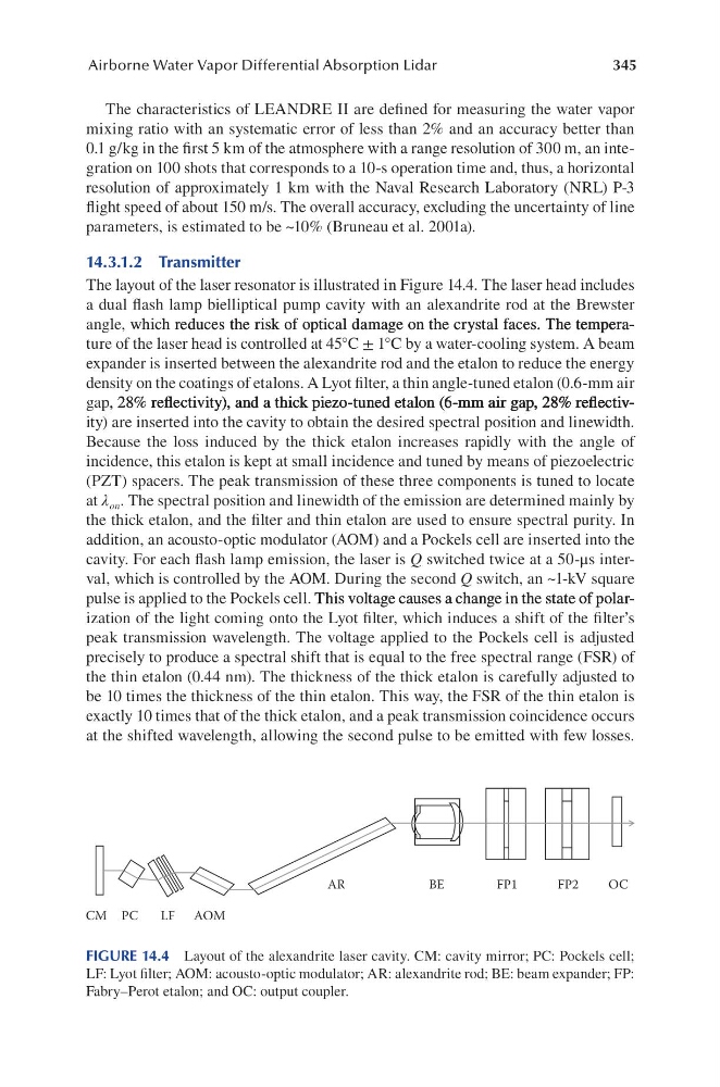
The layout of the laser resonator is illustrated in Figure 14.4. The laser head includes
a dual flash lamp bielliptical pump cavity with an alexandrite rod at the Brewster
angle, which reduces the risk of optical damage on the crystal faces. The temperawhich reduces the risk of optical damage on the crystal faces. The temperareduces the risk of optical damage on the crystal faces. The temperaThe temperahe temperature of the laser head is controlled at 45°C ± 1°C by a water-cooling system. A beam
expander is inserted between the alexandrite rod and the etalon to reduce the energy
density on the coatings of etalons. A Lyot filter, a thin angle-tuned etalon (0.6-mm air
gap, 28% refl ectivity), and a thick piezo-tuned etalon (6-mm air gap, 28% refl ectiv, 28% refl ectivity), and a thick piezo-tuned etalon (6-mm air gap, 28% refl ectiv28% refl ectivity), and a thick piezo-tuned etalon (6-mm air gap, 28% refl ectivrefl ectivity), and a thick piezo-tuned etalon (6-mm air gap, 28% refl ectivreflectivity), and a thick piezo-tuned etalon (6-mm air gap, 28% refl ectiv), and a thick piezo-tuned etalon (6-mm air gap, 28% refl ectivand a thick piezo-tuned etalon (6-mm air gap, 28% refl ectiv(6-mm air gap, 28% refl ectiv6-mm air gap, 28% refl ectivair gap, 28% refl ectivair gap, 28% refl ectiv, 28% refl ectiv28% reflectivity) are inserted into the cavity to obtain the desired spectral position and linewidth.
Because the loss induced by the thick etalon increases rapidly with the angle of
incidence, this etalon is kept at small incidence and tuned by means of piezoelectric
(PZT) spacers. The peak transmission of these three components is tuned to locate
at λ on . The spectral position and linewidth of the emission are determined mainly by
the thick etalon, and the filter and thin etalon are used to ensure spectral purity. In
addition, an acousto-optic modulator (AOM) and a Pockels cell are inserted into the
cavity. For each flash lamp emission, the laser is Q switched twice at a 50-μs interval, which is controlled by the AOM. During the second Q switch, an ~1-kV square
pulse is applied to the Pockels cell. This voltage causes a change in the state of polarThis voltage causes a change in the state of polarThis voltage causes a change in the state of polarization of the light coming onto the Lyot filter, which induces a shift of the filter’s
peak transmission wavelength. The voltage applied to the Pockels cell is adjusted
precisely to produce a spectral shift that is equal to the free spectral range (FSR) of
the thin etalon (0.44 nm). The thickness of the thick etalon is carefully adjusted to
be 10 times the thickness of the thin etalon. This way, the FSR of the thin etalon is
exactly 10 times that of the thick etalon, and a peak transmission coincidence occurs
at the shifted wavelength, allowing the second pulse to be emitted with few losses.
CM PC
LF AOM
AR
BE
FP1
FP2
OC
FIGURE 14.4 Layout of the alexandrite laser cavity. CM: cavity mirror; PC: Pockels cell;
LF: Lyot filter; AOM: acousto-optic modulator; AR: alexandrite rod; BE: beam expander; FP:
Fabry–Perot etalon; and OC: output coupler.
Airborne Water Vapor Differential Absorption Lidar
The characteristics of LEANDRE II are defined for measuring the water vapor
mixing ratio with an systematic error of less than 2% and an accuracy better than
0.1 g/kg in the first 5 km of the atmosphere with a range resolution of 300 m, an integration on 100 shots that corresponds to a 10-s operation time and, thus, a horizontal
resolution of approximately 1 km with the Naval Research Laboratory (NRL) P-3
flight speed of about 150 m/s. The overall accuracy, excluding the uncertainty of line
parameters, is estimated to be ~10% (Bruneau et al. 2001a).
14.3.1.2 Transmitter
The layout of the laser resonator is illustrated in Figure 14.4. The laser head includes
a dual flash lamp bielliptical pump cavity with an alexandrite rod at the Brewster
angle, which reduces the risk of optical damage on the crystal faces. The temperawhich reduces the risk of optical damage on the crystal faces. The temperareduces the risk of optical damage on the crystal faces. The temperaThe temperahe temperature of the laser head is controlled at 45°C ± 1°C by a water-cooling system. A beam
expander is inserted between the alexandrite rod and the etalon to reduce the energy
density on the coatings of etalons. A Lyot filter, a thin angle-tuned etalon (0.6-mm air
gap, 28% refl ectivity), and a thick piezo-tuned etalon (6-mm air gap, 28% refl ectiv, 28% refl ectivity), and a thick piezo-tuned etalon (6-mm air gap, 28% refl ectiv28% refl ectivity), and a thick piezo-tuned etalon (6-mm air gap, 28% refl ectivrefl ectivity), and a thick piezo-tuned etalon (6-mm air gap, 28% refl ectivreflectivity), and a thick piezo-tuned etalon (6-mm air gap, 28% refl ectiv), and a thick piezo-tuned etalon (6-mm air gap, 28% refl ectivand a thick piezo-tuned etalon (6-mm air gap, 28% refl ectiv(6-mm air gap, 28% refl ectiv6-mm air gap, 28% refl ectivair gap, 28% refl ectivair gap, 28% refl ectiv, 28% refl ectiv28% reflectivity) are inserted into the cavity to obtain the desired spectral position and linewidth.
Because the loss induced by the thick etalon increases rapidly with the angle of
incidence, this etalon is kept at small incidence and tuned by means of piezoelectric
(PZT) spacers. The peak transmission of these three components is tuned to locate
at λ on . The spectral position and linewidth of the emission are determined mainly by
the thick etalon, and the filter and thin etalon are used to ensure spectral purity. In
addition, an acousto-optic modulator (AOM) and a Pockels cell are inserted into the
cavity. For each flash lamp emission, the laser is Q switched twice at a 50-μs interval, which is controlled by the AOM. During the second Q switch, an ~1-kV square
pulse is applied to the Pockels cell. This voltage causes a change in the state of polarThis voltage causes a change in the state of polarThis voltage causes a change in the state of polarization of the light coming onto the Lyot filter, which induces a shift of the filter’s
peak transmission wavelength. The voltage applied to the Pockels cell is adjusted
precisely to produce a spectral shift that is equal to the free spectral range (FSR) of
the thin etalon (0.44 nm). The thickness of the thick etalon is carefully adjusted to
be 10 times the thickness of the thin etalon. This way, the FSR of the thin etalon is
exactly 10 times that of the thick etalon, and a peak transmission coincidence occurs
at the shifted wavelength, allowing the second pulse to be emitted with few losses.
CM PC
LF AOM
AR
BE
FP1
FP2
OC
FIGURE 14.4 Layout of the alexandrite laser cavity. CM: cavity mirror; PC: Pockels cell;
LF: Lyot filter; AOM: acousto-optic modulator; AR: alexandrite rod; BE: beam expander; FP:
Fabry–Perot etalon; and OC: output coupler.