

107
on the measurements of oxygen microprofiles in
sediment/bottom water boundary layers of the
deep sea is the report by Reimers (1978). Jørgensen and Revsbech (1985), subsequently, Archer et
al. (1989) and Gundersen and Jørgensen (1990)
were the first to measure a diffusive boundary
layer using landers. The first in situ incubations
using a lander were carried out by Smith Jr. and
Teal (1973).
Profiles with Microelectrodes
A profile measured in situ with an oxygen
microelectrode has already been presented and
quantitatively evaluated in Figure 3.5. Such measurements became feasible only after oxygen
electrodes had been developed that could measure oxygen concentrations at the sediment/
bottom water boundary layers with a depth
resolution of about 20 to 50 µm. It is also important to note that the measurement is carried out
without being influenced by the oxygen depletion
of the electrode. The development of the electrodes is closely linked to the name of N.P. Revsbech
(Aarhus, Denmark) and is described in the publications of Revsbech et al. (1980), Jørgensen and
Revsbech (1985), Revsbech and Jørgensen (1986),
Revsbech (1989) and Kühl and Revsbech (2001).
The basic construction principle underlying
the function of an oxygen microelectrode is shown
in Figure 3.20, after a publication by Revsbech
(1989). It is evident that such an electrode cannot
be built without considerable practiced skill and
experience - and they have to be either self-made
or purchased at a rather high price. It is furthermore evident that such microelectrodes are extremely sensitive and break easily as, when they
either hit a rather solid zone in the sediment,
contain slight imperfections from manufacturing,
or are handled with the slightest degree of ineptitude.
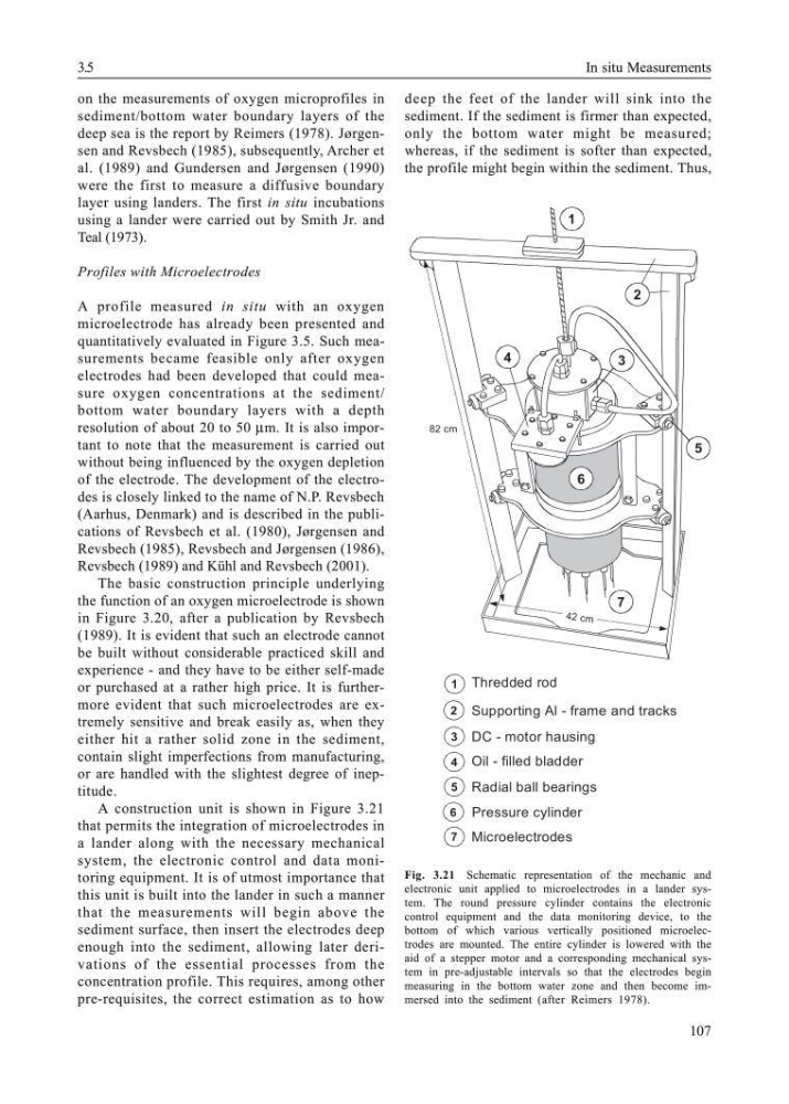
A construction unit is shown in Figure 3.21
that permits the integration of microelectrodes in
a lander along with the necessary mechanical
system, the electronic control and data monitoring equipment. It is of utmost importance that
this unit is built into the lander in such a manner
that the measurements will begin above the
sediment surface, then insert the electrodes deep
enough into the sediment, allowing later derivations of the essential processes from the
concentration profile. This requires, among other
pre-requisites, the correct estimation as to how
deep the feet of the lander will sink into the
sediment. If the sediment is firmer than expected,
only the bottom water might be measured;
whereas, if the sediment is softer than expected,
the profile might begin within the sediment. Thus,
Fig. 3.21 Schematic representation of the mechanic and
electronic unit applied to microelectrodes in a lander system. The round pressure cylinder contains the electronic
control equipment and the data monitoring device, to the
bottom of which various vertically positioned microelectrodes are mounted. The entire cylinder is lowered with the
aid of a stepper motor and a corresponding mechanical system in pre-adjustable intervals so that the electrodes begin
measuring in the bottom water zone and then become immersed into the sediment (after Reimers 1978).
42 cm
82 cm
1
2
3
4
7
6
5
Oil - filled bladder
Thredded rod
Supporting Al - frame and tracks
DC - motor hausing
Radial ball bearings
Pressure cylinder
Microelectrodes
1
2
3
4
5
6
7
3.5
In situ Measurements
on the measurements of oxygen microprofiles in
sediment/bottom water boundary layers of the
deep sea is the report by Reimers (1978). Jørgensen and Revsbech (1985), subsequently, Archer et
al. (1989) and Gundersen and Jørgensen (1990)
were the first to measure a diffusive boundary
layer using landers. The first in situ incubations
using a lander were carried out by Smith Jr. and
Teal (1973).
Profiles with Microelectrodes
A profile measured in situ with an oxygen
microelectrode has already been presented and
quantitatively evaluated in Figure 3.5. Such measurements became feasible only after oxygen
electrodes had been developed that could measure oxygen concentrations at the sediment/
bottom water boundary layers with a depth
resolution of about 20 to 50 µm. It is also important to note that the measurement is carried out
without being influenced by the oxygen depletion
of the electrode. The development of the electrodes is closely linked to the name of N.P. Revsbech
(Aarhus, Denmark) and is described in the publications of Revsbech et al. (1980), Jørgensen and
Revsbech (1985), Revsbech and Jørgensen (1986),
Revsbech (1989) and Kühl and Revsbech (2001).
The basic construction principle underlying
the function of an oxygen microelectrode is shown
in Figure 3.20, after a publication by Revsbech
(1989). It is evident that such an electrode cannot
be built without considerable practiced skill and
experience - and they have to be either self-made
or purchased at a rather high price. It is furthermore evident that such microelectrodes are extremely sensitive and break easily as, when they
either hit a rather solid zone in the sediment,
contain slight imperfections from manufacturing,
or are handled with the slightest degree of ineptitude.
A construction unit is shown in Figure 3.21
that permits the integration of microelectrodes in
a lander along with the necessary mechanical
system, the electronic control and data monitoring equipment. It is of utmost importance that
this unit is built into the lander in such a manner
that the measurements will begin above the
sediment surface, then insert the electrodes deep
enough into the sediment, allowing later derivations of the essential processes from the
concentration profile. This requires, among other
pre-requisites, the correct estimation as to how
deep the feet of the lander will sink into the
sediment. If the sediment is firmer than expected,
only the bottom water might be measured;
whereas, if the sediment is softer than expected,
the profile might begin within the sediment. Thus,
Fig. 3.21 Schematic representation of the mechanic and
electronic unit applied to microelectrodes in a lander system. The round pressure cylinder contains the electronic
control equipment and the data monitoring device, to the
bottom of which various vertically positioned microelectrodes are mounted. The entire cylinder is lowered with the
aid of a stepper motor and a corresponding mechanical system in pre-adjustable intervals so that the electrodes begin
measuring in the bottom water zone and then become immersed into the sediment (after Reimers 1978).
42 cm
82 cm
1
2
3
4
7
6
5
Oil - filled bladder
Thredded rod
Supporting Al - frame and tracks
DC - motor hausing
Radial ball bearings
Pressure cylinder
Microelectrodes
1
2
3
4
5
6
7
3.5
In situ Measurements