

Precipitation at the Ground: Radar Techniques
279
12.2 Radar Technology
12.2.1 Principles of radar measurement
The principles of radar and the observation of weather phenomena were established in the
1940's. Since that time great strides have been made in improving equipment, signal and data
processing and its interpretation. The interested reader should consult some of the texts for
greater detail. Good references are: Skolnik (1970) for engineering and equipment aspects;
Sauvageot (1982), Battan (1981) and Collier (1989) for meteorological phenomena and applications; Atlas (1964, 1990) for general review; Rinehart (1991) for modern techniques; and
Doviak and Zrnic (1993) for Doppler radar principles and applications. A brief summary of the
principles follows.
Most meteorological radars are pulsed radars, that is, electromagnetic waves at fixed preferred
frequencies are transmitted from a directional antenna into the atmosphere in a rapid succession
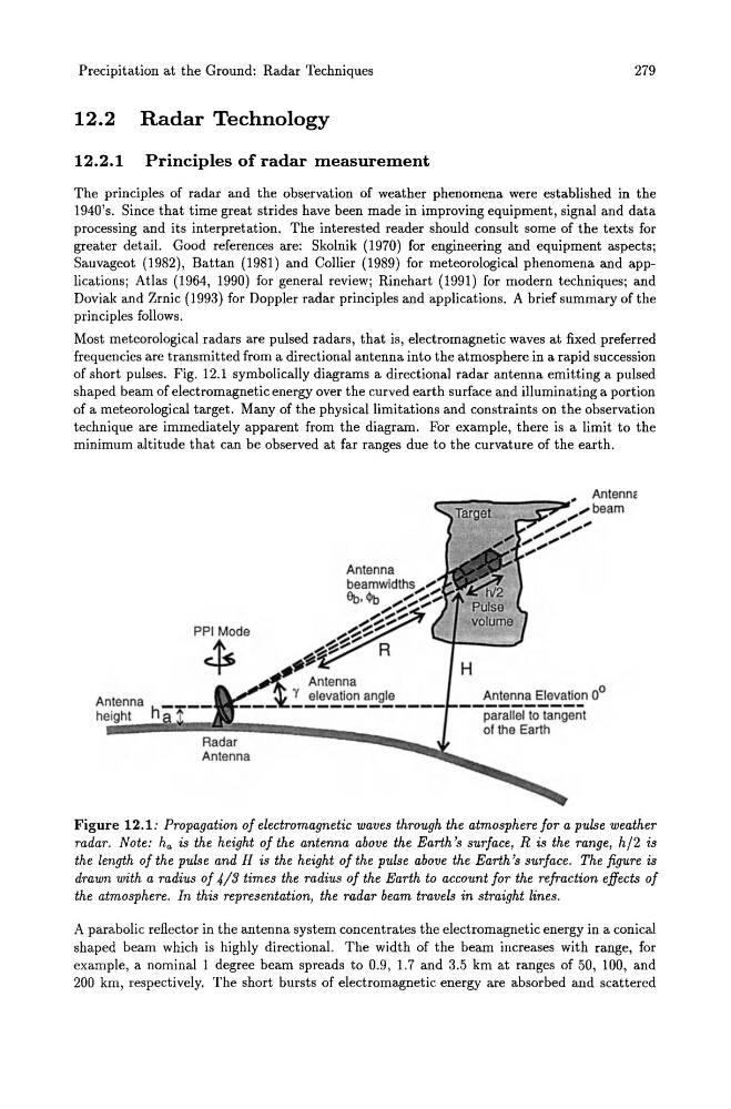
of short pulses. Fig. 12.1 symbolically diagrams a directional radar antenna emitting a pulsed
shaped beam of electromagnetic energy over the curved earth surface and illuminating a portion
of a meteorological target. Many of the physical limitations and constraints on the observation
technique are immediately apparent from the diagram. For example, there is a limit to the
minimum altitude that can be observed at far ranges due to the curvature of the earth.
Antenna
height
Rada~ r """""""""",,~~
Antenna
Antenna Elevation 0 0
---------- parallel to tangent
of the Earth
Figure 12.1: Propagation of electromagnetic waves through the atmosphere for a pulse weather
radar. Note: ha is the height of the antenna above the Earth's surface, R is the range, h /2 is
the length of the pulse and H is the height of the pulse above the Earth's surface. The figure is
drawn with a radius of 4/3 times the radius of the Earth to account for the refraction effects of
the atmosphere. In this representation, the radar beam travels in straight lines.
A parabolic reflector in the antenna system concentrates the electromagnetic energy in a conical
shaped beam which is highly directional. The width of the beam increases with range, for
example, a nominal 1 degree beam spreads to 0.9, 1.7 and 3.5 km at ranges of 50, 100, and
200 km, respectively. The short bursts of electromagnetic energy are absorbed and scattered
279
12.2 Radar Technology
12.2.1 Principles of radar measurement
The principles of radar and the observation of weather phenomena were established in the
1940's. Since that time great strides have been made in improving equipment, signal and data
processing and its interpretation. The interested reader should consult some of the texts for
greater detail. Good references are: Skolnik (1970) for engineering and equipment aspects;
Sauvageot (1982), Battan (1981) and Collier (1989) for meteorological phenomena and applications; Atlas (1964, 1990) for general review; Rinehart (1991) for modern techniques; and
Doviak and Zrnic (1993) for Doppler radar principles and applications. A brief summary of the
principles follows.
Most meteorological radars are pulsed radars, that is, electromagnetic waves at fixed preferred
frequencies are transmitted from a directional antenna into the atmosphere in a rapid succession
of short pulses. Fig. 12.1 symbolically diagrams a directional radar antenna emitting a pulsed
shaped beam of electromagnetic energy over the curved earth surface and illuminating a portion
of a meteorological target. Many of the physical limitations and constraints on the observation
technique are immediately apparent from the diagram. For example, there is a limit to the
minimum altitude that can be observed at far ranges due to the curvature of the earth.
Antenna
height
Rada~ r """""""""",,~~
Antenna
Antenna Elevation 0 0
---------- parallel to tangent
of the Earth
Figure 12.1: Propagation of electromagnetic waves through the atmosphere for a pulse weather
radar. Note: ha is the height of the antenna above the Earth's surface, R is the range, h /2 is
the length of the pulse and H is the height of the pulse above the Earth's surface. The figure is
drawn with a radius of 4/3 times the radius of the Earth to account for the refraction effects of
the atmosphere. In this representation, the radar beam travels in straight lines.
A parabolic reflector in the antenna system concentrates the electromagnetic energy in a conical
shaped beam which is highly directional. The width of the beam increases with range, for
example, a nominal 1 degree beam spreads to 0.9, 1.7 and 3.5 km at ranges of 50, 100, and
200 km, respectively. The short bursts of electromagnetic energy are absorbed and scattered