

8.2 Grid Generation
221
due to the existence of too many irregular pieces (e.g. coolant flow in an
engine block). Generation of triangular and tetrahedral meshes is easier to
automate, which is one of the reasons for their popularity. One usually specifies mesh points on the bounding surface and proceeds from there towards
the center of the domain. When a surface grid has been created, tetrahedra
that have one base on the surface are generated above it and the process
is continued towards the center of the volume along a marching front; the
entire process is something like solving an equation by a marching procedure
and, indeed, some methods are based on the solution of elliptic or hyperbolic
partial differential equations.
Tetrahedral cells are not desirable near walls if the boundary layer needs
to be resolved because the first grid point must be very close to the wall
while relatively large grid sizes can be used in the directions parallel to the
wall. These requirements lead to long thin tetrahedra, creating problems in
the approximation of diffusive fluxes. For this reason, some grid generation
methods generate first a layer of prisms or hexahedra near solid boundaries,
starting with a triangular or quadrilateral discretization of the surface; on top
of this layer, a tetrahedral mesh is generated automatically in the remaining
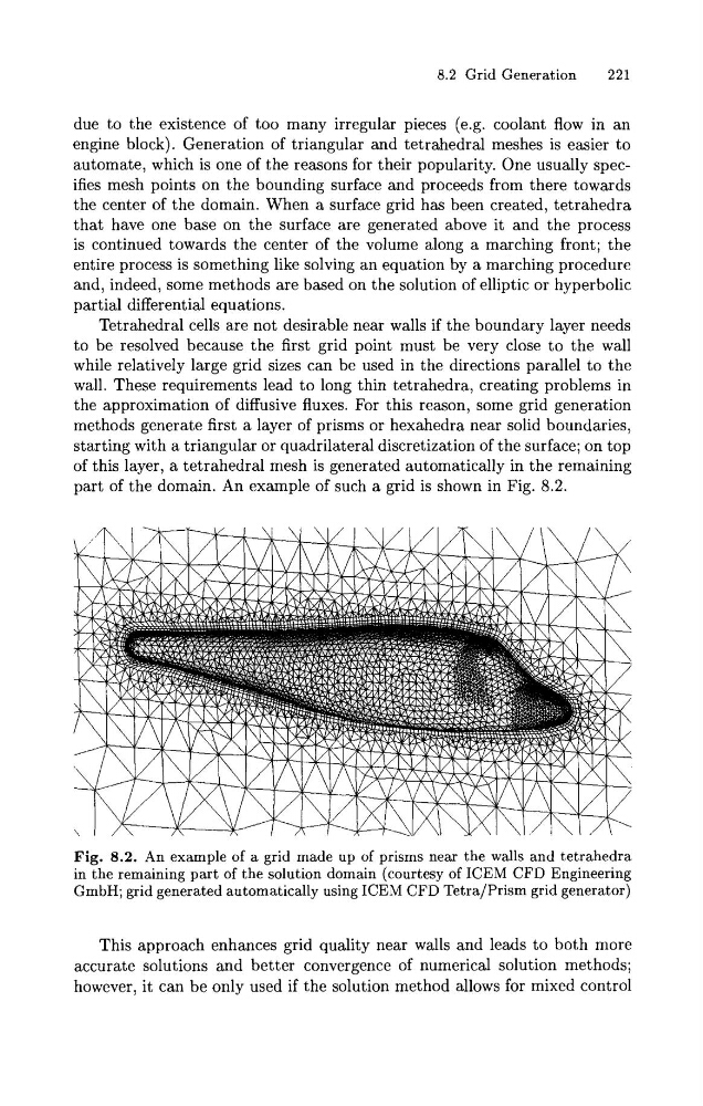
part of the domain. An example of such a grid is shown in Fig. 8.2.
Fig. 8.2. An example of a grid made up of prisms near the walls and tetrahedra
in the remaining part of the solution domain (courtesy of ICEM CFD Engineering
GmbH; grid generated automatically using ICEM CFD Tetra/Prism grid generator)
This approach enhances grid quality near walls and leads to both more
accurate solutions and better convergence of numerical solution methods;
however, it can be only used if the solution method allows for mixed control
221
due to the existence of too many irregular pieces (e.g. coolant flow in an
engine block). Generation of triangular and tetrahedral meshes is easier to
automate, which is one of the reasons for their popularity. One usually specifies mesh points on the bounding surface and proceeds from there towards
the center of the domain. When a surface grid has been created, tetrahedra
that have one base on the surface are generated above it and the process
is continued towards the center of the volume along a marching front; the
entire process is something like solving an equation by a marching procedure
and, indeed, some methods are based on the solution of elliptic or hyperbolic
partial differential equations.
Tetrahedral cells are not desirable near walls if the boundary layer needs
to be resolved because the first grid point must be very close to the wall
while relatively large grid sizes can be used in the directions parallel to the
wall. These requirements lead to long thin tetrahedra, creating problems in
the approximation of diffusive fluxes. For this reason, some grid generation
methods generate first a layer of prisms or hexahedra near solid boundaries,
starting with a triangular or quadrilateral discretization of the surface; on top
of this layer, a tetrahedral mesh is generated automatically in the remaining
part of the domain. An example of such a grid is shown in Fig. 8.2.
Fig. 8.2. An example of a grid made up of prisms near the walls and tetrahedra
in the remaining part of the solution domain (courtesy of ICEM CFD Engineering
GmbH; grid generated automatically using ICEM CFD Tetra/Prism grid generator)
This approach enhances grid quality near walls and leads to both more
accurate solutions and better convergence of numerical solution methods;
however, it can be only used if the solution method allows for mixed control