

2.7 Laminar and TUrbulent Flow in Ducts
c.t)
o
~ 1000.0
~
.:
'§
B 100.0
]
.~
';;j
a
~
10.0
1.0
0.1
,
/ /
/ '
/
/
v
69
"
"
,
V
/
/
,
V
10
100
1000
10000
100000 1000000
Buoyancy index
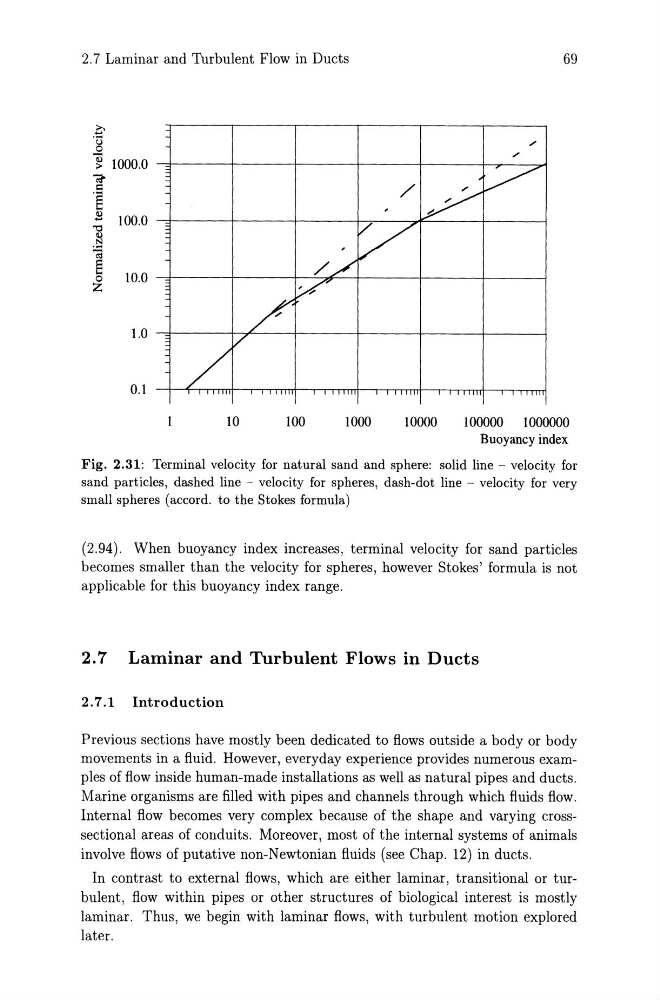
Fig. 2.31: Terminal velocity for natural sand and sphere: solid line - velocity for
sand particles, dashed line - velocity for spheres, dash-dot line - velocity for very
small spheres (accord. to the Stokes formula)
(2.94). When buoyancy index increases, terminal velocity for sand particles
becomes smaller than the velocity for spheres, however Stokes' formula is not
applicable for this buoyancy index range.
2.7 Laminar and Turbulent Flows in Ducts
2.7.1 Introduction
Previous sections have mostly been dedicated to flows outside a body or body
movements in a fluid. However, everyday experience provides numerous examples of flow inside human-made installations as well as natural pipes and ducts.
Marine organisms are filled with pipes and channels through which fluids flow.
Internal flow becomes very complex because of the shape and varying crosssectional areas of conduits. Moreover, most of the internal systems of animals
involve flows of putative non-Newtonian fluids (see Chap. 12) in ducts.
In contrast to external flows, which are either laminar, transitional or turbulent, flow within pipes or other structures of biological interest is mostly
laminar. Thus, we begin with laminar flows, with turbulent motion explored
later.
c.t)
o
~ 1000.0
~
.:
'§
B 100.0
]
.~
';;j
a
~
10.0
1.0
0.1
,
/ /
/ '
/
/
v
69
"
"
,
V
/
/
,
V
10
100
1000
10000
100000 1000000
Buoyancy index
Fig. 2.31: Terminal velocity for natural sand and sphere: solid line - velocity for
sand particles, dashed line - velocity for spheres, dash-dot line - velocity for very
small spheres (accord. to the Stokes formula)
(2.94). When buoyancy index increases, terminal velocity for sand particles
becomes smaller than the velocity for spheres, however Stokes' formula is not
applicable for this buoyancy index range.
2.7 Laminar and Turbulent Flows in Ducts
2.7.1 Introduction
Previous sections have mostly been dedicated to flows outside a body or body
movements in a fluid. However, everyday experience provides numerous examples of flow inside human-made installations as well as natural pipes and ducts.
Marine organisms are filled with pipes and channels through which fluids flow.
Internal flow becomes very complex because of the shape and varying crosssectional areas of conduits. Moreover, most of the internal systems of animals
involve flows of putative non-Newtonian fluids (see Chap. 12) in ducts.
In contrast to external flows, which are either laminar, transitional or turbulent, flow within pipes or other structures of biological interest is mostly
laminar. Thus, we begin with laminar flows, with turbulent motion explored
later.