

14.2 Tides and Waves in Mangrove Forests
region 1
x==o
Z == -h
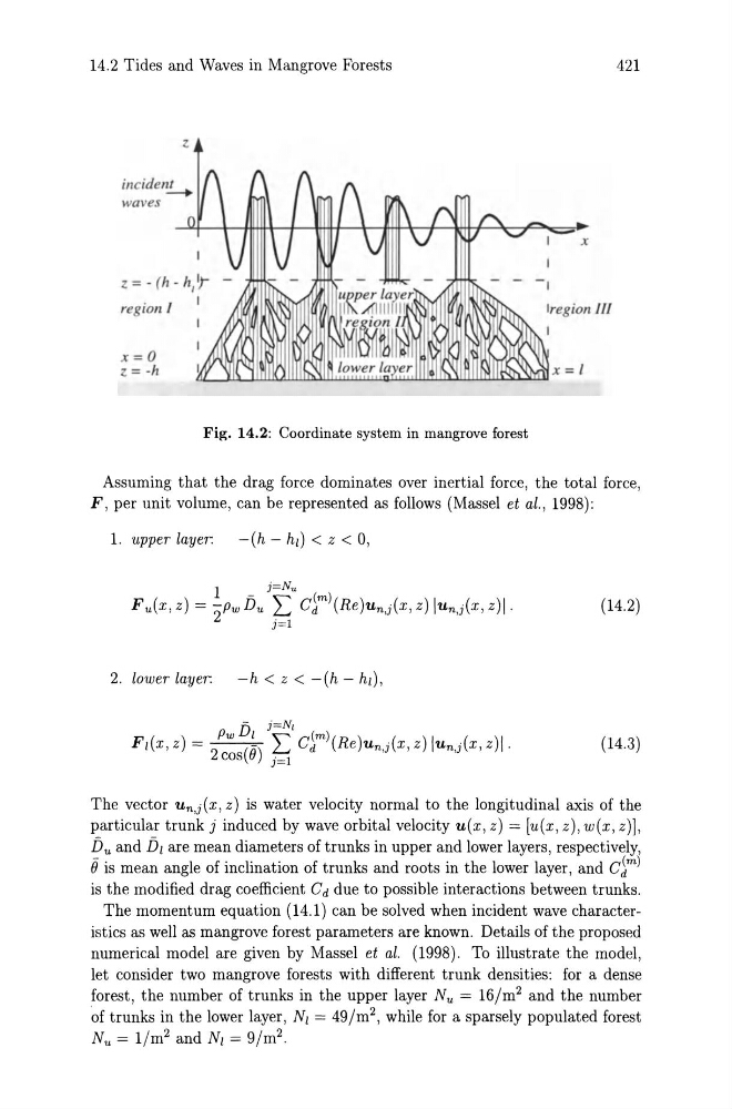
Fig. 14.2: Coordinate system in mangrove forest
421
x
Iregion 1/1
Assuming that the drag force dominates over inertial force, the total force,
F, per unit volume, can be represented as follows (Massel et al., 1998):
1. upper layer:
-(h - hi) < z < 0,
(14.2)
2. lower layer:
-h < z < -(h - hi),
( ) Pw151 j~l (m)( ) ( )1 ( )1
FIX, Z =
( ) ~ Cd Re Un j X, Z Un j X, Z .
2 cos () j=l
'
,
(14.3)
The vector Un,j(X, z) is water velocity normal to the longitudinal axis of the
particular trunk j induced by wave orbital velocity u(x, z) = [u(x, z), w(x, z)],
15u and 151 are mean diameters of trunks in upper and lower layers, respectively,
e is mean angle of inclination of trunks and roots in the lower layer, and C~m)
is the modified drag coefficient Cd due to possible interactions between trunks.
The momentum equation (14.1) can be solved when incident wave characteristics as well as mangrove forest parameters are known. Details of the proposed
numerical model are given by Massel et al. (1998). To illustrate the model,
let consider two mangrove forests with different trunk densities: for a dense
forest, the number of trunks in the upper layer Nu = 161m 2 and the number
of trunks in the lower layer, Nl = 491m2, while for a sparsely populated forest
Nu = 11m 2 and NI = 91m 2 .
region 1
x==o
Z == -h
Fig. 14.2: Coordinate system in mangrove forest
421
x
Iregion 1/1
Assuming that the drag force dominates over inertial force, the total force,
F, per unit volume, can be represented as follows (Massel et al., 1998):
1. upper layer:
-(h - hi) < z < 0,
(14.2)
2. lower layer:
-h < z < -(h - hi),
( ) Pw151 j~l (m)( ) ( )1 ( )1
FIX, Z =
( ) ~ Cd Re Un j X, Z Un j X, Z .
2 cos () j=l
'
,
(14.3)
The vector Un,j(X, z) is water velocity normal to the longitudinal axis of the
particular trunk j induced by wave orbital velocity u(x, z) = [u(x, z), w(x, z)],
15u and 151 are mean diameters of trunks in upper and lower layers, respectively,
e is mean angle of inclination of trunks and roots in the lower layer, and C~m)
is the modified drag coefficient Cd due to possible interactions between trunks.
The momentum equation (14.1) can be solved when incident wave characteristics as well as mangrove forest parameters are known. Details of the proposed
numerical model are given by Massel et al. (1998). To illustrate the model,
let consider two mangrove forests with different trunk densities: for a dense
forest, the number of trunks in the upper layer Nu = 161m 2 and the number
of trunks in the lower layer, Nl = 491m2, while for a sparsely populated forest
Nu = 11m 2 and NI = 91m 2 .