

78
2. Basic Finite-Difference Methods
(b) ,\
I
I
I
I
I
I
I
,
····t .....
I /
I
., /
\
,
- /
I -
\
\ \ ,
\
\
\
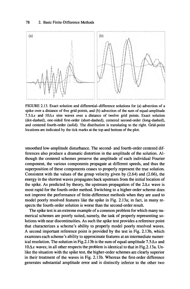
FIGURE 2.13. Exact solution and differential-difference solutions for (a) advection of a
spike overa distanceof five grid points,and (b) advection of the sum of equal-amplitude
7.5l1x and 1OI1x sine waves over a distance of twelve grid points. Exact solution
(dot-dashed), one-sided first-order (short-dashed), centered second-order (long-dashed),
and centered fourth-order (solid). The distribution is translating to the right. Grid-point
locations are indicated by the tick marksat the top and bottomof the plot.
smoothed low-amplitude disturbance. The second- and fourth-order centered differences also produce a dramatic distortion in the amplitude of the solution. AIthough the centered schemes preserve the amplitude of each individual Fourier
component, the various components propagate at different speeds, and thus the
superposition of these components ceases to properly represent the true solution.
Consistent with the values of the group velocity given by (2.64) and (2.66), the
energy in the shortest waves propagates back upstream from the initiallocation of
the spike . As predicted by theory, the upstream propagation of the
wave is
most rapid for the fourth-order method. Switching to a higher-order scheme does
not improve the performance of finite-difference methods when they are used to
model poorly resolved features like the spike in Fig. 2.13a; in fact, in many respects the fourth-order solution is worse than the second-order result.
The spike test is an extreme example of a common problem for which many numerical schemes are poorly suited, namely, the task of properly representing solutions with near discontinuities. As such the spike test provides a reference point
that characterizes a scheme's ability to properly model poorly resolved waves.
A second important reference point is provided by the test in Fig. 2.13b, which
exarnines each scheme's ability to approximate features at an intermediate numerical resolution. The solution in Fig.2.13b is the sum of equal-amplitude
and
I
waves; in all other respects the problem is identical to that in Fig.2.13a. Unlike the situation with the spike test, the higher-order schemes are clearly superior
in their treatment of the waves in Fig. 2.13b. Whereas the first-order difference
generates substantial amplitude error and is distinct1y inferior to the other two
2. Basic Finite-Difference Methods
(b) ,\
I
I
I
I
I
I
I
,
····t .....
I /
I
., /
\
,
- /
I -
\
\ \ ,
\
\
\
FIGURE 2.13. Exact solution and differential-difference solutions for (a) advection of a
spike overa distanceof five grid points,and (b) advection of the sum of equal-amplitude
7.5l1x and 1OI1x sine waves over a distance of twelve grid points. Exact solution
(dot-dashed), one-sided first-order (short-dashed), centered second-order (long-dashed),
and centered fourth-order (solid). The distribution is translating to the right. Grid-point
locations are indicated by the tick marksat the top and bottomof the plot.
smoothed low-amplitude disturbance. The second- and fourth-order centered differences also produce a dramatic distortion in the amplitude of the solution. AIthough the centered schemes preserve the amplitude of each individual Fourier
component, the various components propagate at different speeds, and thus the
superposition of these components ceases to properly represent the true solution.
Consistent with the values of the group velocity given by (2.64) and (2.66), the
energy in the shortest waves propagates back upstream from the initiallocation of
the spike . As predicted by theory, the upstream propagation of the
wave is
most rapid for the fourth-order method. Switching to a higher-order scheme does
not improve the performance of finite-difference methods when they are used to
model poorly resolved features like the spike in Fig. 2.13a; in fact, in many respects the fourth-order solution is worse than the second-order result.
The spike test is an extreme example of a common problem for which many numerical schemes are poorly suited, namely, the task of properly representing solutions with near discontinuities. As such the spike test provides a reference point
that characterizes a scheme's ability to properly model poorly resolved waves.
A second important reference point is provided by the test in Fig. 2.13b, which
exarnines each scheme's ability to approximate features at an intermediate numerical resolution. The solution in Fig.2.13b is the sum of equal-amplitude
and
I
waves; in all other respects the problem is identical to that in Fig.2.13a. Unlike the situation with the spike test, the higher-order schemes are clearly superior
in their treatment of the waves in Fig. 2.13b. Whereas the first-order difference
generates substantial amplitude error and is distinct1y inferior to the other two