

246
W.M. Sanders III and J.W. Falco
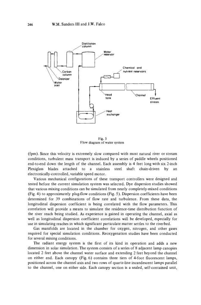
Chemical and
nutrient reservoirs
Fig. 3
Flow diagram of water system
(fpm). Since this velocity is extremely slow compared with most natural river or stream
conditions, turbulent mass transport is induced by a series of paddle wheels positioned
end-to-end down the length of the channel. Each assembly is 4 feet long with six 2-inch
Plexiglass blades attached to a stainless steel shaft chain-driven by an
electronically-con trolled, variable speed motor.
Various mechanical configurations of these transport controllers were designed and
tested before the current simulation system was selected. Dye dispersion studies showed
that various mixing conditions can be simulated from nearly completely-mixed conditions
(Fig. 4) to approximately plug-flow conditions (Fig. 5). Dispersion coefficients have been
determined for 39 combinations of flow rate and turbulence. From these data, the
longitudinal dispersion coefficient is being correlated with the flow parameters. This
correlation will provide a means to simulate the residence-time distribution function of
the river reach being studied. As experience is gained in operating the channel, axial as
well as longitudinal dispersion coefficient correlations will be developed, especially for
use in simulating reaches in which significant particulate matter settles to the riverbed.
Gas manifolds are located in the chamber for oxygen, nitrogen, and other gases
required for special simulation conditions. Reoxygenation studies have been conducted
for several mixing conditions.
The radiant energy system is the first of its kind in operation and adds a new
dimension in solar simulation. The system consists of a series of 8 adjacent lamp canopies
located 2 feet above the channel water surface and extending 2 feet beyond the channel
on either end. Each canopy (Fig. 6) contains three tiers of 4-foot fluorescent lamps,
positioned across the channel axis and two rows of quartz-line incandescent lamps parallel
to the channel, one on either side. Each canopy section is a sealed, self-contained unit,
W.M. Sanders III and J.W. Falco
Chemical and
nutrient reservoirs
Fig. 3
Flow diagram of water system
(fpm). Since this velocity is extremely slow compared with most natural river or stream
conditions, turbulent mass transport is induced by a series of paddle wheels positioned
end-to-end down the length of the channel. Each assembly is 4 feet long with six 2-inch
Plexiglass blades attached to a stainless steel shaft chain-driven by an
electronically-con trolled, variable speed motor.
Various mechanical configurations of these transport controllers were designed and
tested before the current simulation system was selected. Dye dispersion studies showed
that various mixing conditions can be simulated from nearly completely-mixed conditions
(Fig. 4) to approximately plug-flow conditions (Fig. 5). Dispersion coefficients have been
determined for 39 combinations of flow rate and turbulence. From these data, the
longitudinal dispersion coefficient is being correlated with the flow parameters. This
correlation will provide a means to simulate the residence-time distribution function of
the river reach being studied. As experience is gained in operating the channel, axial as
well as longitudinal dispersion coefficient correlations will be developed, especially for
use in simulating reaches in which significant particulate matter settles to the riverbed.
Gas manifolds are located in the chamber for oxygen, nitrogen, and other gases
required for special simulation conditions. Reoxygenation studies have been conducted
for several mixing conditions.
The radiant energy system is the first of its kind in operation and adds a new
dimension in solar simulation. The system consists of a series of 8 adjacent lamp canopies
located 2 feet above the channel water surface and extending 2 feet beyond the channel
on either end. Each canopy (Fig. 6) contains three tiers of 4-foot fluorescent lamps,
positioned across the channel axis and two rows of quartz-line incandescent lamps parallel
to the channel, one on either side. Each canopy section is a sealed, self-contained unit,