

160
R.P. Mathur and N.S. Grewal
where
w
Di
D 2
c
z
r
t
is average seepage velocity cm/sec.
is longitudinal dispersion coefficient cm
2 /sec.
is lateral dispersion coefficient cm
2 /sec.
is average concentration of material of time t mg/L.
is distance along the direction of flow
is radial distance, perpendicular to the flow s axis cm
is time
The above equation has been solved for a set of boundary conditions which were available
in the experimental model used by statistical analysis of the experimental data.
Experimental set up
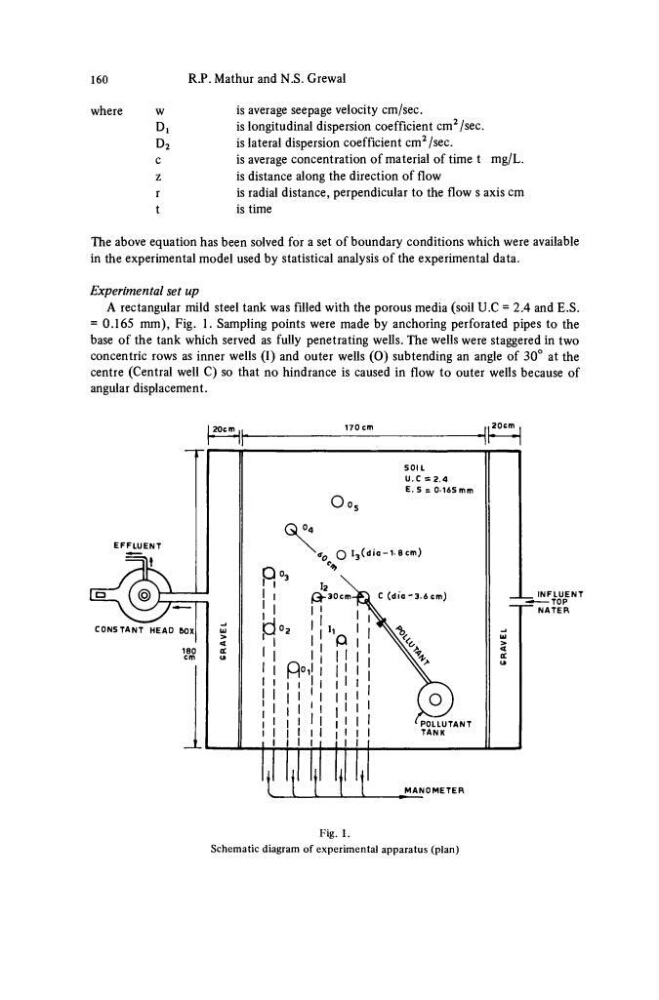
A rectangular mild steel tank was filled with the porous media (soil U.C = 2.4 and E.S.
= 0.165 mm), Fig. 1. Sampling points were made by anchoring perforated pipes to the
base of the tank which served as fully penetrating wells. The wells were staggered in two
concentric rows as inner wells (I) and outer wells (0) subtending an angle of 30° at the
centre (Central well C) so that no hindrance is caused in flow to outer wells because of
angular displacement.
20cm .
I
1
T T ϊ Ί
MANOMETER
Fig. 1.
Schematic diagram of experimental apparatus (plan)
R.P. Mathur and N.S. Grewal
where
w
Di
D 2
c
z
r
t
is average seepage velocity cm/sec.
is longitudinal dispersion coefficient cm
2 /sec.
is lateral dispersion coefficient cm
2 /sec.
is average concentration of material of time t mg/L.
is distance along the direction of flow
is radial distance, perpendicular to the flow s axis cm
is time
The above equation has been solved for a set of boundary conditions which were available
in the experimental model used by statistical analysis of the experimental data.
Experimental set up
A rectangular mild steel tank was filled with the porous media (soil U.C = 2.4 and E.S.
= 0.165 mm), Fig. 1. Sampling points were made by anchoring perforated pipes to the
base of the tank which served as fully penetrating wells. The wells were staggered in two
concentric rows as inner wells (I) and outer wells (0) subtending an angle of 30° at the
centre (Central well C) so that no hindrance is caused in flow to outer wells because of
angular displacement.
20cm .
I
1
T T ϊ Ί
MANOMETER
Fig. 1.
Schematic diagram of experimental apparatus (plan)