

6.1. Advection Dominated Problems
153
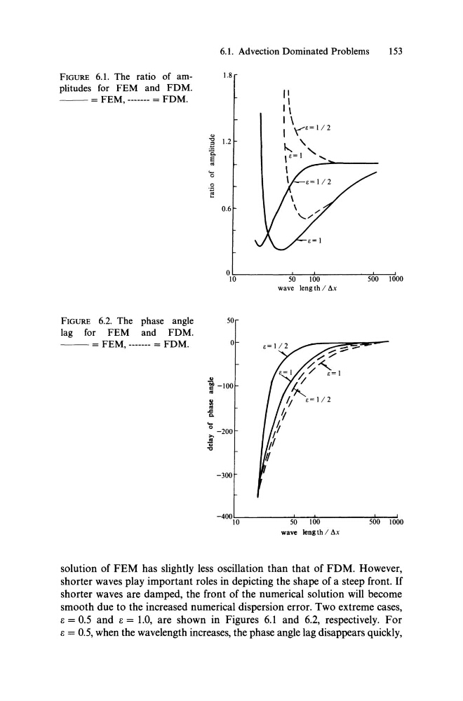
FIGURE 6.1. The ratio of am1.8
plitudes for FEM and FDM.
- - = FEM, ------- = FDM.
0.6
"
1\
I \
I \"","8 = 1/2
" '
,8=1 ' ......
, ~---\
°1\:-0-----,5~0--:-100:':::----~5~00;---;-;!10·00
wave leng th / Öx
FIGURE 6.2. The phase angle
50
lag for FEM and FDM.
- - = FEM, ------- = FDM.
0
j -100
..
...
0 _ 200
i
-300
-400~10~-----5~0--~10~0--------~5~00;--1~000
wave leng th / Öx
solution of FEM has slightly less oscillation than that of FDM. However,
shorter waves play important roles in depicting the shape of a steep front. If
shorter waves are damped, the front of the numerical solution will become
smooth due to the increased numerical dispersion error. Two extreme cases,
e = 0.5 and e = 1.0, are shown in Figures 6.1 and 6.2, respectively. For
e = 0.5, when the wavelength increases, the phase angle lag disappears quickly,
153
FIGURE 6.1. The ratio of am1.8
plitudes for FEM and FDM.
- - = FEM, ------- = FDM.
0.6
"
1\
I \
I \"","8 = 1/2
" '
,8=1 ' ......
, ~---\
°1\:-0-----,5~0--:-100:':::----~5~00;---;-;!10·00
wave leng th / Öx
FIGURE 6.2. The phase angle
50
lag for FEM and FDM.
- - = FEM, ------- = FDM.
0
j -100
..
...
0 _ 200
i
-300
-400~10~-----5~0--~10~0--------~5~00;--1~000
wave leng th / Öx
solution of FEM has slightly less oscillation than that of FDM. However,
shorter waves play important roles in depicting the shape of a steep front. If
shorter waves are damped, the front of the numerical solution will become
smooth due to the increased numerical dispersion error. Two extreme cases,
e = 0.5 and e = 1.0, are shown in Figures 6.1 and 6.2, respectively. For
e = 0.5, when the wavelength increases, the phase angle lag disappears quickly,