

708
15 Optics
Newton’s Rings (in Reflected Light)
Radius of the mth ring (r m ) for the convex lens of radius R is given by
r m =
√
mλR
(dark rings, m = 0, 1, 2, . . .)
(15.27a)
2t = mλ
(dark rings)
(15.27b)
r m =
m +
1
2
λ
(bright rings, m = 0, 1, 2, . . .)
(15.28a)
2t = (m + ½)λ
(bright rings)
(15.28b)
where t is the thickness of air gap.
Michelson’s Interferometer
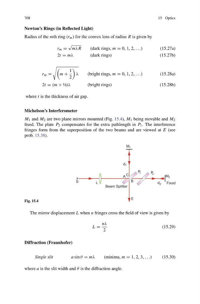
M 1 and M 2 are two plane mirrors mounted (Fig. 15.4), M 1 being movable and M 2
fixed. The plate P 2 compensates for the extra pathlength in P 1 . The interference
fringes form from the superposition of the two beams and are viewed at E (see
prob. 15.38).
Fig. 15.4
The mirror displacement L when n fringes cross the field of view is given by
L =
nλ
2
(15.29)
Diffraction (Fraunhofer)
Single slit
a sin θ = mλ
(minima, m = 1, 2, 3, . . .)
(15.30)
where a is the slit width and θ is the diffraction angle.