

640
14 Electromagnetism II
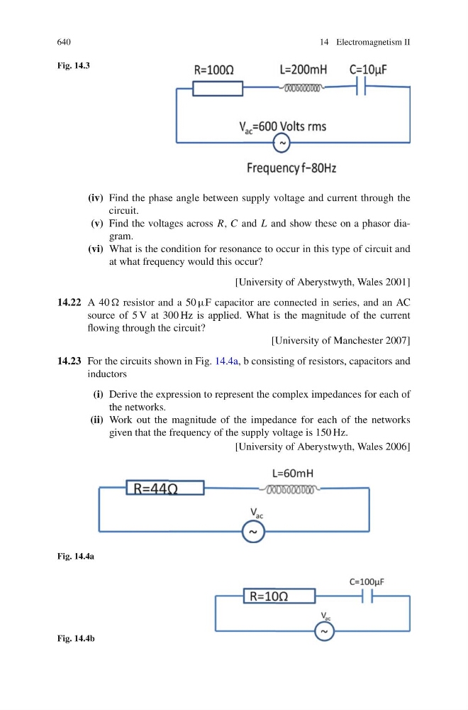
Fig. 14.3
(iv) Find the phase angle between supply voltage and current through the
circuit.
(v) Find the voltages across R, C and L and show these on a phasor diagram.
(vi) What is the condition for resonance to occur in this type of circuit and
at what frequency would this occur?
[University of Aberystwyth, Wales 2001]
14.22 A 40 resistor and a 50 μF capacitor are connected in series, and an AC
source of 5 V at 300 Hz is applied. What is the magnitude of the current
flowing through the circuit?
[University of Manchester 2007]
14.23 For the circuits shown in Fig. 14.4a, b consisting of resistors, capacitors and
inductors
(i) Derive the expression to represent the complex impedances for each of
the networks.
(ii) Work out the magnitude of the impedance for each of the networks
given that the frequency of the supply voltage is 150 Hz.
[University of Aberystwyth, Wales 2006]
Fig. 14.4a
Fig. 14.4b