

14.2 Problems
639
14.17 Set up the equation for the RC circuit in series and show that the input power
is the sum of the powers delivered to the inductor and capacitor.
14.18 Set up the equation for the RLC circuit in parallel and show that at any time
the Joule heat in the resistor comes from the energy stored in the inductor
and capacitor.
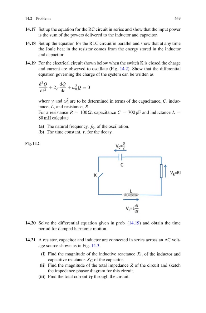
14.19 For the electrical circuit shown below when the switch K is closed the charge
and current are observed to oscillate (Fig. 14.2). Show that the differential
equation governing the charge of the system can be written as
d 2 Q
dt 2 + 2γ
dQ
dt
+ ω
2
0 Q = 0
where γ and ω 2
0 are to be determined in terms of the capacitance, C, inductance, L, and resistance, R.
For a resistance R = 100 , capacitance C = 700 pF and inductance L =
80 mH calculate
(a) The natural frequency, f 0 , of the oscillation.
(b) The time constant, τ , for the decay.
Fig. 14.2
14.20 Solve the differential equation given in prob. (14.19) and obtain the time
period for damped harmonic motion.
14.21 A resistor, capacitor and inductor are connected in series across an AC voltage source shown as in Fig. 14.3.
(i) Find the magnitude of the inductive reactance X L of the inductor and
capacitive reactance X C of the capacitor.
(ii) Find the magnitude of the total impedance Z of the circuit and sketch
the impedance phasor diagram for this circuit.
(iii) Find the total current I T through the circuit.