

552
12 Electric Circuits
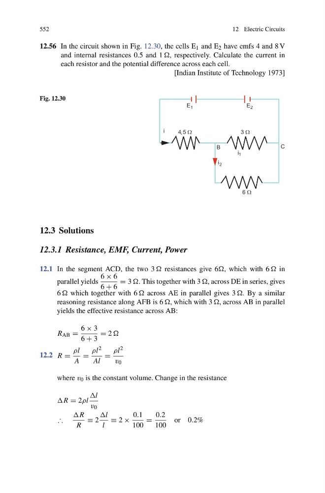
12.56 In the circuit shown in Fig. 12.30, the cells E 1 and E 2 have emfs 4 and 8 V
and internal resistances 0.5 and 1 , respectively. Calculate the current in
each resistor and the potential difference across each cell.
[Indian Institute of Technology 1973]
Fig. 12.30
12.3 Solutions
12.3.1 Resistance, EMF, Current, Power
12.1 In the segment ACD, the two 3 resistances give 6, which with 6 in
parallel yields
6 × 6
6 + 6
= 3 . This together with 3 , across DE in series, gives
6 which together with 6 across AE in parallel gives 3 . By a similar
reasoning resistance along AFB is 6 , which with 3 , across AB in parallel
yields the effective resistance across AB:
R AB =
6 × 3
6 + 3
= 2
12.2 R =
ρl
A
=
ρl 2
Al
=
ρl 2
v 0
where v 0 is the constant volume. Change in the resistance
R = 2ρl
l
v 0
∴
R
R
≡ 2
l
l
≡ 2 ×
0.1
100
=
0.2
100
or 0.2%