

787
27-2 M ULTILOOP CIRCUITS
Replacing the parallel combination with R eq , we obtain the
simplified circuit of Fig. 27-12d. Applying the loop rule to
this circuit counterclockwise from point b, we have
Ᏹ row Ϫ iR w Ϫ iR eq ϭ 0.
Solving for i and substituting the known data, we find
(Answer)
If the head or tail of the eel is near a fish, some of this
current could pass along a narrow path through the fish,
stunning or killing it.
ϭ 0.927 A Ϸ 0.93 A.
i ϭ
Ᏹ row
R w ϩ R eq
ϭ
750 V
800 ⍀ ϩ 8.93 ⍀
(b) How much current i row travels through each row of
Fig. 27-12a?
KEY IDEA
Because the rows are identical, the current into and out of
the eel is evenly divided among them.
Calculation: Thus, we write
(Answer)
Thus, the current through each row is small, so that the eel
need not stun or kill itself when it stuns or kills a fish.
i row ϭ
i
140
ϭ
0.927 A
140
ϭ 6.6 ϫ 10
Ϫ3
A.
Combining equations: We now have a system of two equations (Eqs. 27-27 and 27-28) in two unknowns (i 1 and i 2 ) to
solve either “by hand” (which is easy enough here) or with a
“math package.” (One solution technique is Cramer’s rule,
given in Appendix E.) We find
i 1 ϭ Ϫ0.50 A.
(27-29)
(The minus sign signals that our arbitrary choice of direction
for i 1 in Fig. 27-13 is wrong, but we must wait to correct it.)
Substituting i 1 ϭ Ϫ0.50 A into Eq. 27-28 and solving for
i 2 then give us
i 2 ϭ 0.25 A.
(Answer)
With Eq. 27-26 we then find that
i 3 ϭ i 1 ϩ i 2 ϭ Ϫ0.50 A ϩ 0.25 A
ϭ Ϫ0.25 A.
The positive answer we obtained for i 2 signals that our choice of
direction for that current is correct. However, the negative answers for i 1 and i 3 indicate that our choices for those currents are
wrong.Thus, as a last step here, we correct the answers by reversing the arrows for i 1 and i 3 in Fig. 27-13 and then writing
i 1 ϭ 0.50 A and i 3 ϭ 0.25 A.
(Answer)
Caution: Always make any such correction as the last step
and not before calculating all the currents.
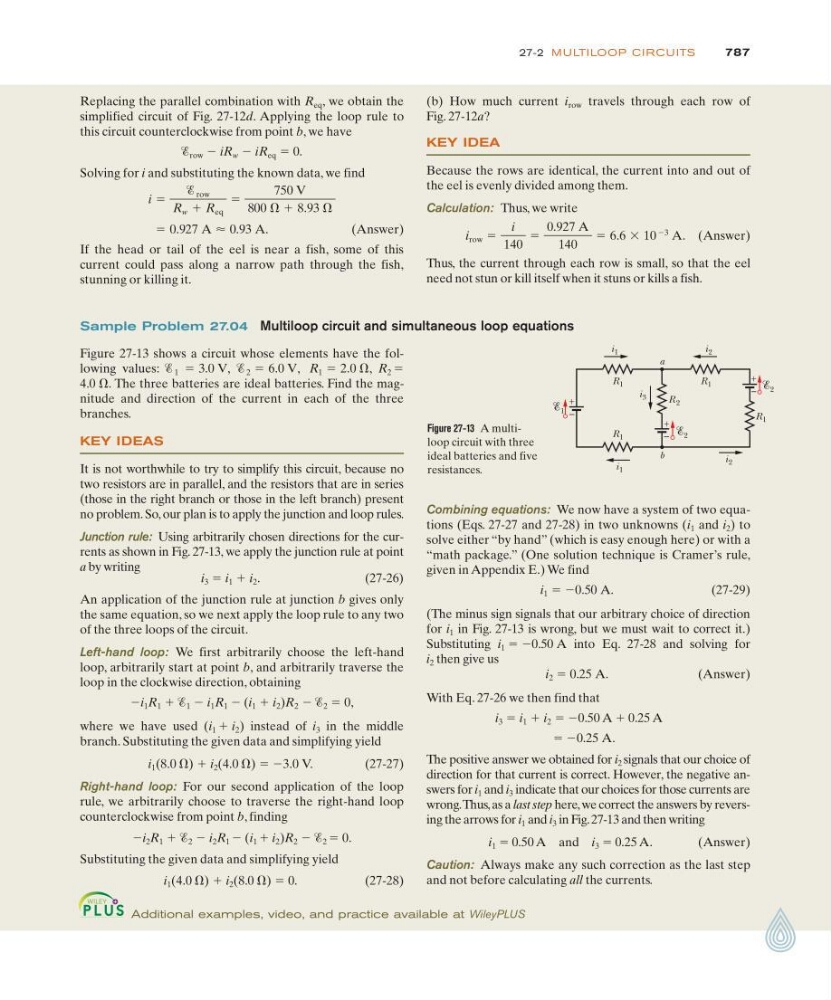
Figure 27-13 shows a circuit whose elements have the following values:
The three batteries are ideal batteries. Find the magnitude and direction of the current in each of the three
branches.
KEY IDEAS
It is not worthwhile to try to simplify this circuit, because no
two resistors are in parallel, and the resistors that are in series
(those in the right branch or those in the left branch) present
no problem. So, our plan is to apply the junction and loop rules.
Junction rule: Using arbitrarily chosen directions for the currents as shown in Fig. 27-13, we apply the junction rule at point
a by writing
i 3 ϭ i 1 ϩ i 2 .
( 2 7 - 2 6 )
An application of the junction rule at junction b gives only
the same equation, so we next apply the loop rule to any two
of the three loops of the circuit.
Left-hand loop: We first arbitrarily choose the left-hand
loop, arbitrarily start at point b, and arbitrarily traverse the
loop in the clockwise direction, obtaining
Ϫi 1 R 1 ϩ Ᏹ 1 Ϫ i 1 R 1 Ϫ (i 1 ϩ i 2 )R 2 Ϫ Ᏹ 2 ϭ 0,
where we have used (i 1 ϩ i 2 ) instead of i 3 in the middle
branch. Substituting the given data and simplifying yield
i 1 (8.0 ⍀) ϩ i 2 (4.0 ⍀) ϭ Ϫ3.0 V.
(27-27)
Right-hand loop: For our second application of the loop
rule, we arbitrarily choose to traverse the right-hand loop
counterclockwise from point b, finding
Ϫi 2 R 1 ϩ Ᏹ 2 Ϫ i 2 R 1 Ϫ (i 1 ϩ i 2 )R 2 Ϫ Ᏹ 2 ϭ 0.
Substituting the given data and simplifying yield
i 1 (4.0 ⍀) ϩ i 2 (8.0 ⍀) ϭ 0.
(27-28)
4.0 ⍀.
R 2 ϭ
R 1 ϭ 2.0 ⍀,
Ᏹ 1 ϭ 3.0 V, Ᏹ 2 ϭ 6.0 V,
Figure 27-13 A multiloop circuit with three
ideal batteries and five
resistances.
+
–
1
2
R 2
R 1
R 1
R 1
R 1
+
–
+
– 2
i 1
i 2
i 1
i 2
a
b
i 3
Additional examples, video, and practice available at WileyPLUS
Sample Problem 27.04 Multiloop circuit and simultaneous loop equations