

786
CHAPTE R 27 CI RCU ITS
The total resistance R row along a row is the sum of the internal resistances of the 5000 electroplaques:
R row ϭ 5000r ϭ (5000)(0.25 ⍀) ϭ 1250 ⍀.
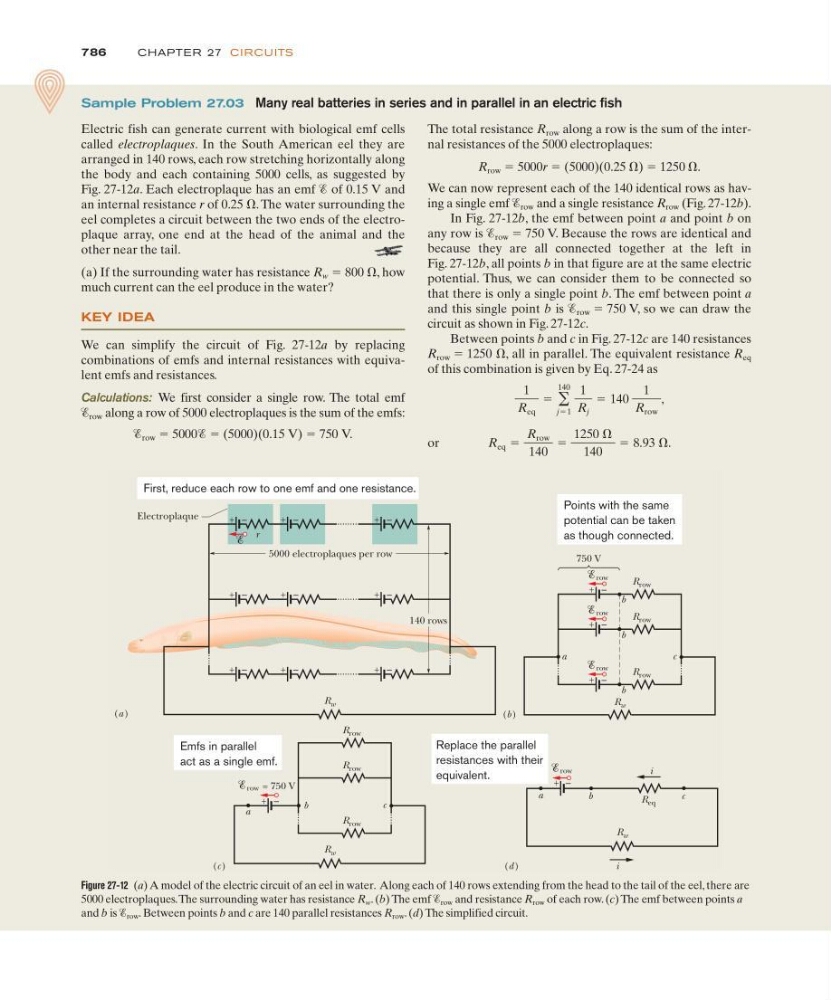
We can now represent each of the 140 identical rows as having a single emf Ᏹ row and a single resistance R row (Fig. 27-12b).
In Fig. 27-12b, the emf between point a and point b on
any row is Ᏹ row ϭ 750 V. Because the rows are identical and
because they are all connected together at the left in
Fig. 27-12b, all points b in that figure are at the same electric
potential. Thus, we can consider them to be connected so
that there is only a single point b. The emf between point a
and this single point b is Ᏹ row ϭ 750 V, so we can draw the
circuit as shown in Fig. 27-12c.
Between points b and c in Fig. 27-12c are 140 resistances
R row ϭ 1250 ⍀, all in parallel. The equivalent resistance R eq
of this combination is given by Eq. 27-24 as
or
R eq ϭ
R row
140
ϭ
1250 ⍀
140
ϭ 8.93 ⍀.
1
R eq
ϭ ͚
140
jϭ1
1
R j
ϭ 140
1
R row
,
Sample Problem 27.03 Many real batteries in series and in parallel in an electric fish
Electric fish can generate current with biological emf cells
called electroplaques. In the South American eel they are
arranged in 140 rows, each row stretching horizontally along
the body and each containing 5000 cells, as suggested by
Fig. 27-12a. Each electroplaque has an emf Ᏹ of 0.15 V and
an internal resistance r of 0.25 ⍀. The water surrounding the
eel completes a circuit between the two ends of the electroplaque array, one end at the head of the animal and the
other near the tail.
(a) If the surrounding water has resistance R w ϭ 800 ⍀, how
much current can the eel produce in the water?
KEY IDEA
We can simplify the circuit of Fig. 27-12a by replacing
combinations of emfs and internal resistances with equivalent emfs and resistances.
Calculations: We first consider a single row. The total emf
Ᏹ row along a row of 5000 electroplaques is the sum of the emfs:
Ᏹ row ϭ 5000Ᏹ ϭ (5000)(0.15 V) ϭ 750 V.
Figure 27-12 (a) A model of the electric circuit of an eel in water. Along each of 140 rows extending from the head to the tail of the eel, there are
5000 electroplaques.The surrounding water has resistance R w . (b) The emf Ᏹ row and resistance R row of each row. (c) The emf between points a
and b is Ᏹ row . Between points b and c are 140 parallel resistances R row . (d) The simplified circuit.
R w
i
(b )
a
c
row
R row
row
R row
row
R row
b
b
b
R w
(c )
a
c
row
R row
b
= 750 V
R w
(d )
row
R eq
+ –
i
R w
(a )
r
Electroplaque
5000 electroplaques per row
140 rows
–
+
750 V
–
+
–
+
–
+
–
+
–
+
–
+
–
+
–
+
–
+
–
+
–
+
–
+
R row
R row
a
b
c
First, reduce each row to one emf and one resistance.
Emfs in parallel
act as a single emf.
Replace the parallel
resistances with their
equivalent.
Points with the same
potential can be taken
as though connected.