

Equation 27-18 is a single equation involving three unknowns. To solve the
circuit completely (that is, to find all three currents), we need two more equations
involving those same unknowns. We obtain them by applying the loop rule twice.
In the circuit of Fig. 27-9, we have three loops from which to choose: the left-hand
loop (badb), the right-hand loop (bcdb), and the big loop (badcb). Which two
loops we choose does not matter — let’s choose the left-hand loop and the righthand loop.
If we traverse the left-hand loop in a counterclockwise direction from point
b, the loop rule gives us
Ᏹ 1 Ϫ i 1 R 1 ϩ i 3 R 3 ϭ 0.
(27-19)
If we traverse the right-hand loop in a counterclockwise direction from point b,
the loop rule gives us
Ϫi 3 R 3 Ϫ i 2 R 2 Ϫ Ᏹ 2 ϭ 0.
(27-20)
We now have three equations (Eqs. 27-18, 27-19, and 27-20) in the three unknown
currents, and they can be solved by a variety of techniques.
If we had applied the loop rule to the big loop, we would have obtained
(moving counterclockwise from b) the equation
Ᏹ 1 Ϫ i 1 R 1 Ϫ i 2 R 2 Ϫ Ᏹ 2 ϭ 0.
However, this is merely the sum of Eqs. 27-19 and 27-20.
Resistances in Parallel
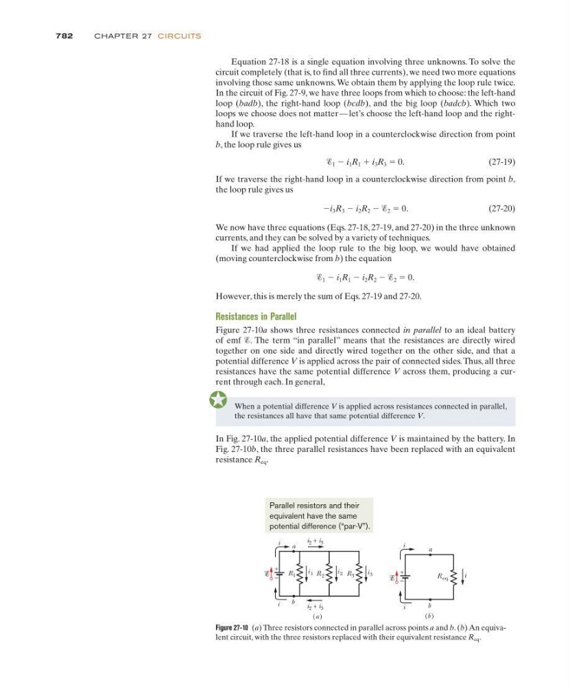
Figure 27-10a shows three resistances connected in parallel to an ideal battery
of emf Ᏹ. The term “in parallel” means that the resistances are directly wired
together on one side and directly wired together on the other side, and that a
potential difference V is applied across the pair of connected sides. Thus, all three
resistances have the same potential difference V across them, producing a current through each. In general,
782
CHAPTE R 27 CI RCU ITS
Figure 27-10 (a) Three resistors connected in parallel across points a and b. (b) An equivalent circuit, with the three resistors replaced with their equivalent resistance R eq .
When a potential difference V is applied across resistances connected in parallel,
the resistances all have that same potential difference V.
In Fig. 27-10a, the applied potential difference V is maintained by the battery. In
Fig. 27-10b, the three parallel resistances have been replaced with an equivalent
resistance R eq .
b
i
R eq
(b )
a
i
+
–
i
R 3
R 1
a
b
i 1
i 3
i 2
+
–
R 2
(a )
i
i
i 2 + i 3
i 2 + i 3
Parallel resistors and their
equivalent have the same
potential difference (“par-V”).