

780
CHAPTE R 27 CI RCU ITS
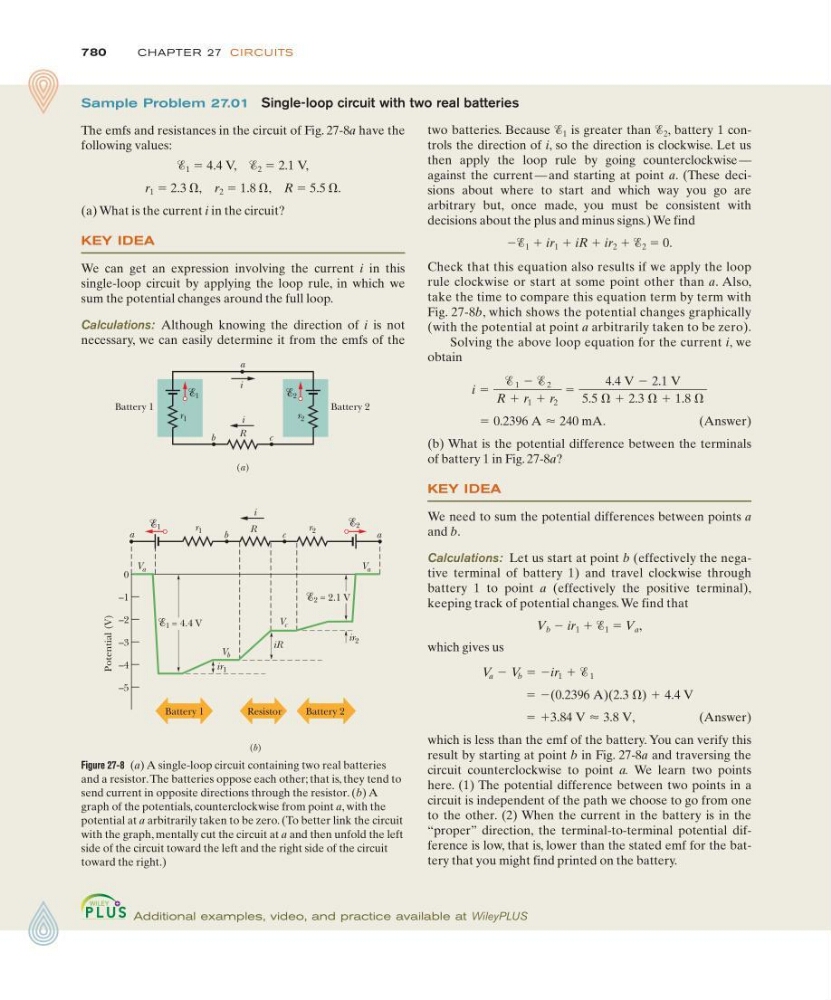
two batteries. Because Ᏹ 1 is greater than Ᏹ 2 , battery 1 controls the direction of i, so the direction is clockwise. Let us
then apply the loop rule by going counterclockwise —
against the current — and starting at point a. (These decisions about where to start and which way you go are
arbitrary but, once made, you must be consistent with
decisions about the plus and minus signs.) We find
ϪᏱ 1 ϩ ir 1 ϩ iR ϩ ir 2 ϩ Ᏹ 2 ϭ 0.
Check that this equation also results if we apply the loop
rule clockwise or start at some point other than a. Also,
take the time to compare this equation term by term with
Fig. 27-8b, which shows the potential changes graphically
(with the potential at point a arbitrarily taken to be zero).
Solving the above loop equation for the current i, we
obtain
(Answer)
(b) What is the potential difference between the terminals
of battery 1 in Fig. 27-8a?
KEY IDEA
We need to sum the potential differences between points a
and b.
Calculations: Let us start at point b (effectively the negative terminal of battery 1) and travel clockwise through
battery 1 to point a (effectively the positive terminal),
keeping track of potential changes. We find that
V b Ϫ ir 1 ϩ Ᏹ 1 ϭ V a ,
which gives us
(Answer)
which is less than the emf of the battery. You can verify this
result by starting at point b in Fig. 27-8a and traversing the
circuit counterclockwise to point a. We learn two points
here. (1) The potential difference between two points in a
circuit is independent of the path we choose to go from one
to the other. (2) When the current in the battery is in the
“proper” direction, the terminal-to-terminal potential difference is low, that is, lower than the stated emf for the battery that you might find printed on the battery.
ϭ ϩ3.84 V Ϸ 3.8 V,
ϭ Ϫ(0.2396 A)(2.3 ⍀) ϩ 4.4 V
V a Ϫ V b ϭ Ϫir 1 ϩ Ᏹ 1
ϭ 0.2396 A Ϸ 240 mA.
i ϭ
Ᏹ 1 Ϫ Ᏹ 2
R ϩ r 1 ϩ r 2
ϭ
4.4 V Ϫ 2.1 V
5.5 ⍀ ϩ 2.3 ⍀ ϩ 1.8 ⍀
Sample Problem 27.01 Single-loop circuit with two real batteries
The emfs and resistances in the circuit of Fig. 27-8a have the
following values:
Ᏹ 1 ϭ 4.4 V, Ᏹ 2 ϭ 2.1 V,
r 1 ϭ 2.3 ⍀, r 2 ϭ 1.8 ⍀, R ϭ 5.5 ⍀.
(a) What is the current i in the circuit?
KEY IDEA
We can get an expression involving the current i in this
single-loop circuit by applying the loop rule, in which we
sum the potential changes around the full loop.
Calculations: Although knowing the direction of i is not
necessary, we can easily determine it from the emfs of the
Additional examples, video, and practice available at WileyPLUS
Figure 27-8 (a) A single-loop circuit containing two real batteries
and a resistor. The batteries oppose each other; that is, they tend to
send current in opposite directions through the resistor. (b) A
graph of the potentials, counterclockwise from point a, with the
potential at a arbitrarily taken to be zero. (To better link the circuit
with the graph, mentally cut the circuit at a and then unfold the left
side of the circuit toward the left and the right side of the circuit
toward the right.)
R
Battery 1
r 1
i
(a)
a
Battery 2
1
b
c
2
r 2
i
a
b
c
a
r 2
R
r 1
i
1
2
Battery 1
Battery 2
Resistor
V a
0
–1
–2
–3
–4
–5
1 = 4.4 V
ir 1
iR
ir 2
2 = 2.1 V
V b
V a
V c
Potential (V)
(b)