

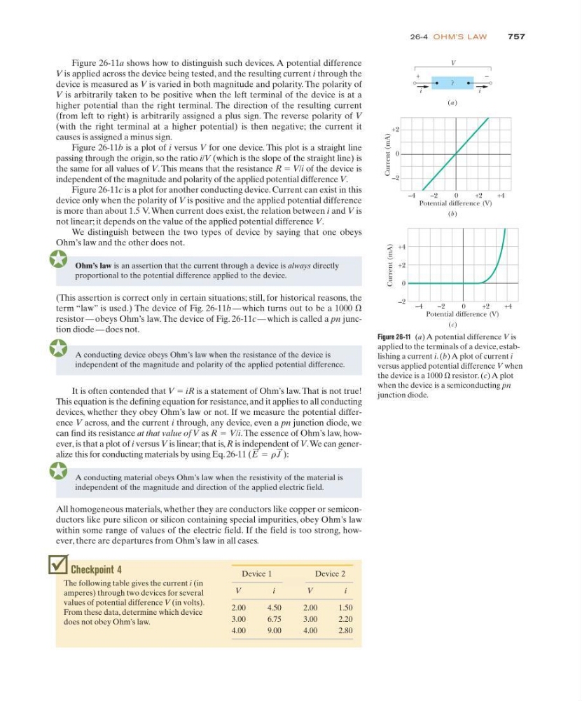
Figure 26-11a shows how to distinguish such devices. A potential difference
V is applied across the device being tested, and the resulting current i through the
device is measured as V is varied in both magnitude and polarity. The polarity of
V is arbitrarily taken to be positive when the left terminal of the device is at a
higher potential than the right terminal. The direction of the resulting current
(from left to right) is arbitrarily assigned a plus sign. The reverse polarity of V
(with the right terminal at a higher potential) is then negative; the current it
causes is assigned a minus sign.
Figure 26-11b is a plot of i versus V for one device. This plot is a straight line
passing through the origin, so the ratio i/V (which is the slope of the straight line) is
the same for all values of V. This means that the resistance R ϭ V/i of the device is
independent of the magnitude and polarity of the applied potential difference V.
Figure 26-11c is a plot for another conducting device. Current can exist in this
device only when the polarity of V is positive and the applied potential difference
is more than about 1.5 V. When current does exist, the relation between i and V is
not linear; it depends on the value of the applied potential difference V.
We distinguish between the two types of device by saying that one obeys
Ohm’s law and the other does not.
757
26-4 OH M’S L AW
+2
0
–2
Current (mA)
Potential difference (V)
–2
0
+2
+4
+4
+2
0
–2
Current (mA)
–4
–2
0
+2
+4
(a )
(b )
(c )
V
?
i
+
–
i
Potential difference (V)
–4
Figure 26-11 (a) A potential difference V is
applied to the terminals of a device, establishing a current i. (b) A plot of current i
versus applied potential difference V when
the device is a 1000 ⍀ resistor. (c) A plot
when the device is a semiconducting pn
junction diode.
(This assertion is correct only in certain situations; still, for historical reasons, the
term “law” is used.) The device of Fig. 26-11b — which turns out to be a 1000 ⍀
resistor — obeys Ohm’s law. The device of Fig. 26-11c — which is called a pn junction diode — does not.
Ohm’s law is an assertion that the current through a device is always directly
proportional to the potential difference applied to the device.
A conducting device obeys Ohm’s law when the resistance of the device is
independent of the magnitude and polarity of the applied potential difference.
It is often contended that V ϭ iR is a statement of Ohm’s law. That is not true!
This equation is the defining equation for resistance, and it applies to all conducting
devices, whether they obey Ohm’s law or not. If we measure the potential difference V across, and the current i through, any device, even a pn junction diode, we
can find its resistance at that value of V as R V/i. The essence of Ohm’s law, however, is that a plot of i versus V is linear; that is, R is independent of V.We can generalize this for conducting materials by using Eq. 26-11 (E
: ϭ r J
: ):
ϭ
Checkpoint 4
The following table gives the current i (in
amperes) through two devices for several
values of potential difference V (in volts).
From these data, determine which device
does not obey Ohm’s law.
Device 1
Device 2
V
i
V
i
2.00
4.50
2.00
1.50
3.00
6.75
3.00
2.20
4.00
9.00
4.00
2.80
A conducting material obeys Ohm’s law when the resistivity of the material is
independent of the magnitude and direction of the applied electric field.
All homogeneous materials, whether they are conductors like copper or semiconductors like pure silicon or silicon containing special impurities, obey Ohm’s law
within some range of values of the electric field. If the field is too strong, however, there are departures from Ohm’s law in all cases.