

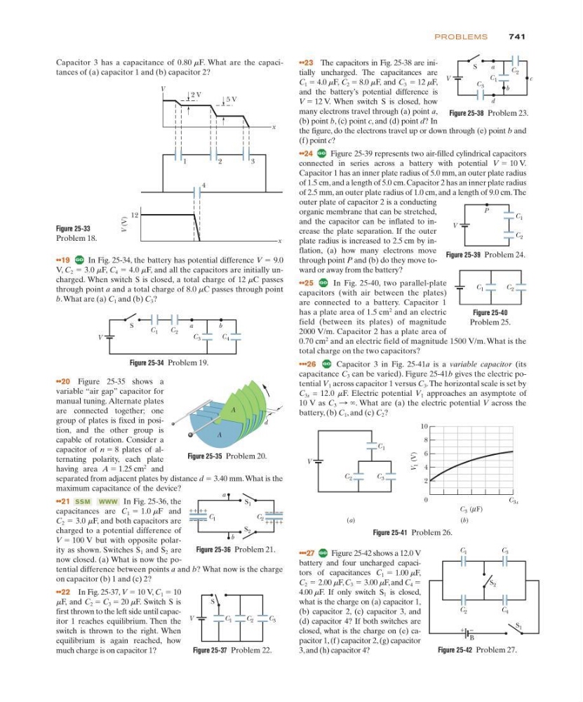
••20 Figure 25-35 shows a
variable “air gap” capacitor for
manual tuning. Alternate plates
are connected together; one
group of plates is fixed in position, and the other group is
capable of rotation. Consider a
capacitor of n ϭ 8 plates of alternating polarity, each plate
having area A ϭ 1.25 cm
2
and
separated from adjacent plates by distance d ϭ 3.40 mm. What is the
maximum capacitance of the device?
••21
In Fig. 25-36, the
capacitances are C 1 1.0 mF and
C 2 3.0 mF, and both capacitors are
charged to a potential difference of
V ϭ 100 V but with opposite polarity as shown. Switches S 1 and S 2 are
now closed. (a) What is now the potential difference between points a and b? What now is the charge
on capacitor (b) 1 and (c) 2?
••22 In Fig. 25-37, V ϭ 10 V, C 1 ϭ 10
mF, and C 2 ϭ C 3 ϭ 20 mF. Switch S is
first thrown to the left side until capacitor 1 reaches equilibrium. Then the
switch is thrown to the right. When
equilibrium is again reached, how
much charge is on capacitor 1?
ϭ
ϭ
WWW
SSM
741
PROB LE M S
•••27
Figure 25-42 shows a 12.0 V
battery and four uncharged capacitors of capacitances C 1 1.00 mF,
C 2 2.00 mF, C 3 3.00 mF, and C 4 ϭ
4.00 mF. If only switch S 1 is closed,
what is the charge on (a) capacitor 1,
(b) capacitor 2, (c) capacitor 3, and
(d) capacitor 4? If both switches are
closed, what is the charge on (e) capacitor 1, (f) capacitor 2, (g) capacitor
3, and (h) capacitor 4?
ϭ
ϭ
ϭ
••19
In Fig. 25-34, the battery has potential difference V 9.0
V, C 2 3.0 mF, C 4 4.0 mF, and all the capacitors are initially uncharged. When switch S is closed, a total charge of 12 mC passes
through point a and a total charge of 8.0 mC passes through point
b.What are (a) C 1 and (b) C 3 ?
ϭ
ϭ
ϭ
Capacitor 3 has a capacitance of 0.80 mF. What are the capacitances of (a) capacitor 1 and (b) capacitor 2?
••23 The capacitors in Fig. 25-38 are initially uncharged. The capacitances are
C 1 ϭ 4.0 mF, C 2 ϭ 8.0 mF, and C 3 ϭ 12 mF,
and the battery’s potential difference is
V ϭ 12 V. When switch S is closed, how
many electrons travel through (a) point a,
(b) point b, (c) point c, and (d) point d? In
the figure, do the electrons travel up or down through (e) point b and
(f) point c?
••24
Figure 25-39 represents two air-filled cylindrical capacitors
connected in series across a battery with potential V 10 V.
Capacitor 1 has an inner plate radius of 5.0 mm, an outer plate radius
of 1.5 cm, and a length of 5.0 cm. Capacitor 2 has an inner plate radius
of 2.5 mm, an outer plate radius of 1.0 cm, and a length of 9.0 cm.The
outer plate of capacitor 2 is a conducting
organic membrane that can be stretched,
and the capacitor can be inflated to increase the plate separation. If the outer
plate radius is increased to 2.5 cm by inflation, (a) how many electrons move
through point P and (b) do they move toward or away from the battery?
••25
In Fig. 25-40, two parallel-plate
capacitors (with air between the plates)
are connected to a battery. Capacitor 1
has a plate area of 1.5 cm
2
and an electric
field (between its plates) of magnitude
2000 V/m. Capacitor 2 has a plate area of
0.70 cm
2
and an electric field of magnitude 1500 V/m. What is the
total charge on the two capacitors?
•••26
Capacitor 3 in Fig. 25-41a is a variable capacitor (its
capacitance C 3 can be varied). Figure 25-41b gives the electric potential V 1 across capacitor 1 versus C 3 .The horizontal scale is set by
C 3s = 12.0 mF. Electric potential V 1 approaches an asymptote of
10 V as C 3 : ϱ. What are (a) the electric potential V across the
battery, (b) C 1 , and (c) C 2 ?
ϭ
V
a
b
S
C 1
C 2
C 3
C 4
Figure 25-34 Problem 19.
A
d
A
Figure 25-35 Problem 20.
+ + + +
– – – –
+ + + +
– – – –
S 2
S 1
C 1
C 2
a
b
Figure 25-36 Problem 21.
S
C 1
C 2
V
C 3
Figure 25-37 Problem 22.
V
a
d
b
c
S
C 2
C 1
C 3
Figure 25-38 Problem 23.
Figure 25-39 Problem 24.
C 1
C 2
V
P
C 2
C 1
Figure 25-40
Problem 25.
V
C 2
C 3
C 1
(a)
(b)
V
1 (V)
10
8
6
4
2
0
C 3 ( F)
µ
C 3s
Figure 25-41 Problem 26.
Figure 25-42 Problem 27.
S 2
C 1
C 3
C 2
C 4
S 1
B
+ –
Figure 25-33
Problem 18.
12
x
x
4
1
2
3
2 V
5 V
V
V (V)