

721
25-2 CALCU L ATI NG TH E CAPACITANCE
at the edges of the plates, taking to be constant throughout the region between
the plates.
We draw a Gaussian surface that encloses just the charge q on the positive
plate, as in Fig. 25-5. From Eq. 25-4 we can then write
q ϭ ´ 0 EA,
( 2 5 - 7 )
where A is the area of the plate.
Equation 25-6 yields
(25-8)
In Eq. 25-8, E can be placed outside the integral because it is a constant; the second integral then is simply the plate separation d.
If we now substitute q from Eq. 25-7 and V from Eq. 25-8 into the relation
q ϭ CV (Eq. 25-1), we find
(parallel-plate capacitor).
(25-9)
Thus, the capacitance does indeed depend only on geometrical factors — namely,
the plate area A and the plate separation d. Note that C increases as we increase
area A or decrease separation d.
As an aside, we point out that Eq. 25-9 suggests one of our reasons for writing
the electrostatic constant in Coulomb’s law in the form 1/4p´ 0 . If we had not
done so, Eq. 25-9 — which is used more often in engineering practice than
Coulomb’s law — would have been less simple in form. We note further that
Eq. 25-9 permits us to express the permittivity constant ´ 0 in a unit more appropriate for use in problems involving capacitors; namely,
´ 0 ϭ 8.85 ϫ 10
Ϫ12
F/m ϭ 8.85 pF/m.
(25-10)
We have previously expressed this constant as
´ 0 ϭ 8.85 ϫ 10
Ϫ12
C
2
/N иm
2
.
( 2 5 - 1 1 )
A Cylindrical Capacitor
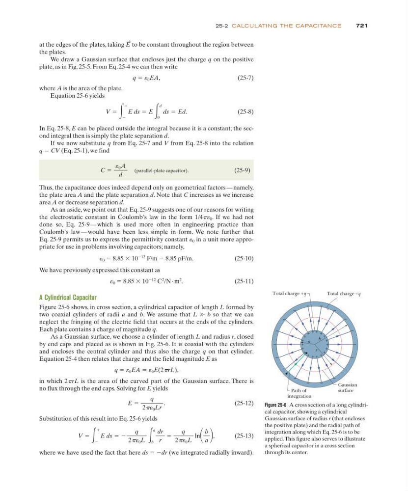
Figure 25-6 shows, in cross section, a cylindrical capacitor of length L formed by
two coaxial cylinders of radii a and b. We assume that L ӷ b so that we can
neglect the fringing of the electric field that occurs at the ends of the cylinders.
Each plate contains a charge of magnitude q.
As a Gaussian surface, we choose a cylinder of length L and radius r, closed
by end caps and placed as is shown in Fig. 25-6. It is coaxial with the cylinders
and encloses the central cylinder and thus also the charge q on that cylinder.
Equation 25-4 then relates that charge and the field magnitude E as
q ϭ ´ 0 EA ϭ ´ 0 E(2prL),
in which 2prL is the area of the curved part of the Gaussian surface. There is
no flux through the end caps. Solving for E yields
(25-12)
Substitution of this result into Eq. 25-6 yields
(25-13)
where we have used the fact that here ds ϭ Ϫdr (we integrated radially inward).
V ϭ ͵
ϩ
Ϫ
E ds ϭ Ϫ
q
2p´ 0 L
͵
a
b
dr
r
ϭ
q
2p´ 0 L
ln
b
a ,
E ϭ
q
2p´ 0 Lr
.
C ϭ
0 A
d
V ϭ ͵
ϩ
Ϫ
E ds ϭ E ͵
d
0
ds ϭ Ed.
E
:
Figure 25-6 A cross section of a long cylindrical capacitor, showing a cylindrical
Gaussian surface of radius r (that encloses
the positive plate) and the radial path of
integration along which Eq. 25-6 is to be
applied. This figure also serves to illustrate
a spherical capacitor in a cross section
through its center.
+
+
+
+
+
+
+
+
+
+
+
+ + + + +
+
+
–
–
–
–
–
–
–
–
–
–
–
–
–
–
–
–
–
–
Path of
integration
Gaussian
surface
a
r
b
Total charge +q
Total charge –q