

Classification Accuracy and Specificity are used to evaluate the overall system
precision. The processes may be formally described by means of Eq. (6) and Eq. (7).
Where, “True Positives” (TP) and “True Negatives” (TN) are correct classifications.
“False Negatives” and ”False Positives” (FP) (FN) are wrong classification results [13].
Accuracy ¼
T P þ T N
T P þ T N þ F P þ F N
 100%:
ð6Þ
Specificity ¼
T N
T N þ F P
:
ð7Þ
3 Results and Discussions
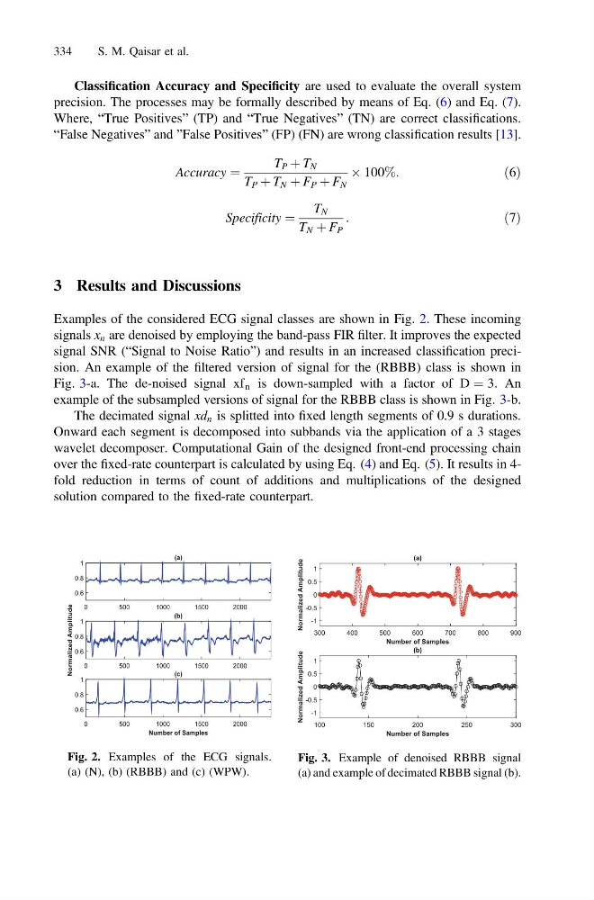
Examples of the considered ECG signal classes are shown in Fig. 2. These incoming
signals x n are denoised by employing the band-pass FIR filter. It improves the expected
signal SNR (“Signal to Noise Ratio”) and results in an increased classification precision. An example of the filtered version of signal for the (RBBB) class is shown in
Fig. 3-a. The de-noised signal xf n is down-sampled with a factor of D ¼ 3. An
example of the subsampled versions of signal for the RBBB class is shown in Fig. 3-b.
The decimated signal xd n is splitted into fixed length segments of 0.9 s durations.
Onward each segment is decomposed into subbands via the application of a 3 stages
wavelet decomposer. Computational Gain of the designed front-end processing chain
over the fixed-rate counterpart is calculated by using Eq. (4) and Eq. (5). It results in 4fold reduction in terms of count of additions and multiplications of the designed
solution compared to the fixed-rate counterpart.
Fig. 2. Examples of the ECG signals.
(a) (N), (b) (RBBB) and (c) (WPW).
Fig. 3. Example of denoised RBBB signal
(a) and example of decimated RBBB signal (b).
334
S. M. Qaisar et al.
precision. The processes may be formally described by means of Eq. (6) and Eq. (7).
Where, “True Positives” (TP) and “True Negatives” (TN) are correct classifications.
“False Negatives” and ”False Positives” (FP) (FN) are wrong classification results [13].
Accuracy ¼
T P þ T N
T P þ T N þ F P þ F N
 100%:
ð6Þ
Specificity ¼
T N
T N þ F P
:
ð7Þ
3 Results and Discussions
Examples of the considered ECG signal classes are shown in Fig. 2. These incoming
signals x n are denoised by employing the band-pass FIR filter. It improves the expected
signal SNR (“Signal to Noise Ratio”) and results in an increased classification precision. An example of the filtered version of signal for the (RBBB) class is shown in
Fig. 3-a. The de-noised signal xf n is down-sampled with a factor of D ¼ 3. An
example of the subsampled versions of signal for the RBBB class is shown in Fig. 3-b.
The decimated signal xd n is splitted into fixed length segments of 0.9 s durations.
Onward each segment is decomposed into subbands via the application of a 3 stages
wavelet decomposer. Computational Gain of the designed front-end processing chain
over the fixed-rate counterpart is calculated by using Eq. (4) and Eq. (5). It results in 4fold reduction in terms of count of additions and multiplications of the designed
solution compared to the fixed-rate counterpart.
Fig. 2. Examples of the ECG signals.
(a) (N), (b) (RBBB) and (c) (WPW).
Fig. 3. Example of denoised RBBB signal
(a) and example of decimated RBBB signal (b).
334
S. M. Qaisar et al.