

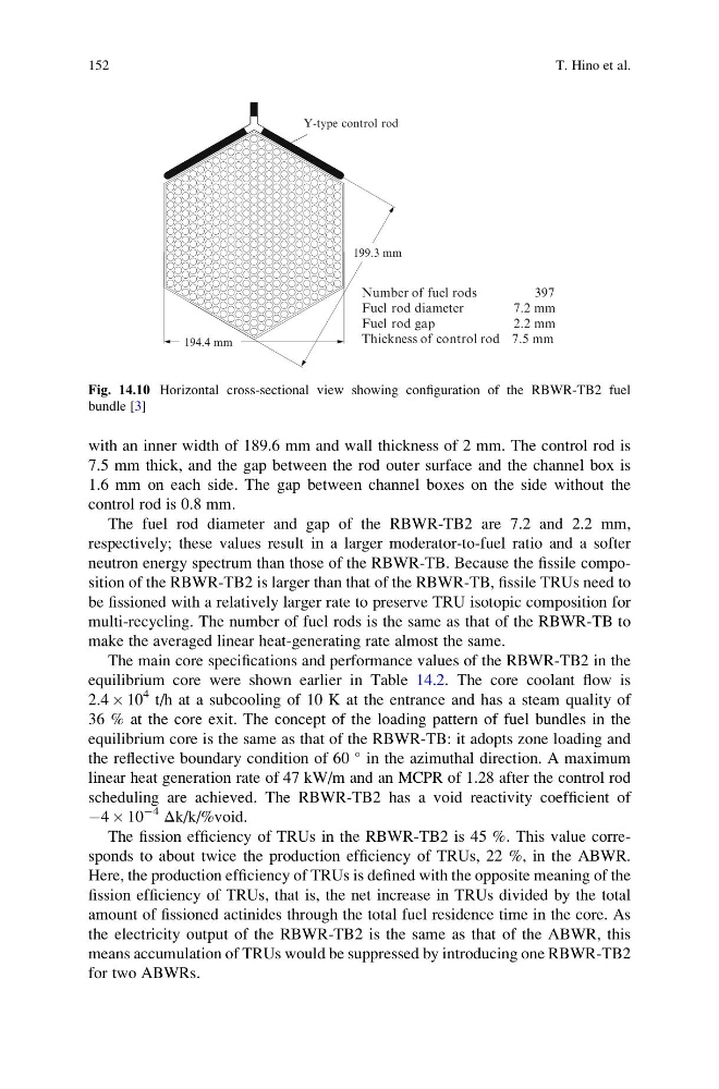
with an inner width of 189.6 mm and wall thickness of 2 mm. The control rod is
7.5 mm thick, and the gap between the rod outer surface and the channel box is
1.6 mm on each side. The gap between channel boxes on the side without the
control rod is 0.8 mm.
The fuel rod diameter and gap of the RBWR-TB2 are 7.2 and 2.2 mm,
respectively; these values result in a larger moderator-to-fuel ratio and a softer
neutron energy spectrum than those of the RBWR-TB. Because the fissile composition of the RBWR-TB2 is larger than that of the RBWR-TB, fissile TRUs need to
be fissioned with a relatively larger rate to preserve TRU isotopic composition for
multi-recycling. The number of fuel rods is the same as that of the RBWR-TB to
make the averaged linear heat-generating rate almost the same.
The main core specifications and performance values of the RBWR-TB2 in the
equilibrium core were shown earlier in Table 14.2. The core coolant flow is
2.4 Â 10
4 t/h at a subcooling of 10 K at the entrance and has a steam quality of
36 % at the core exit. The concept of the loading pattern of fuel bundles in the
equilibrium core is the same as that of the RBWR-TB: it adopts zone loading and
the reflective boundary condition of 60
in the azimuthal direction. A maximum
linear heat generation rate of 47 kW/m and an MCPR of 1.28 after the control rod
scheduling are achieved. The RBWR-TB2 has a void reactivity coefficient of
À4 Â 10
À4
Δk/k/%void.
The fission efficiency of TRUs in the RBWR-TB2 is 45 %. This value corresponds to about twice the production efficiency of TRUs, 22 %, in the ABWR.
Here, the production efficiency of TRUs is defined with the opposite meaning of the
fission efficiency of TRUs, that is, the net increase in TRUs divided by the total
amount of fissioned actinides through the total fuel residence time in the core. As
the electricity output of the RBWR-TB2 is the same as that of the ABWR, this
means accumulation of TRUs would be suppressed by introducing one RBWR-TB2
for two ABWRs.
Y-type control rod
Number of fuel rods
397
Fuel rod diameter
7.2 mm
Fuel rod gap
2.2 mm
Thickness of control rod 7.5 mm
194.4 mm
199.3 mm
Fig. 14.10 Horizontal cross-sectional view showing configuration of the RBWR-TB2 fuel
bundle [3]
152
T. Hino et al.
7.5 mm thick, and the gap between the rod outer surface and the channel box is
1.6 mm on each side. The gap between channel boxes on the side without the
control rod is 0.8 mm.
The fuel rod diameter and gap of the RBWR-TB2 are 7.2 and 2.2 mm,
respectively; these values result in a larger moderator-to-fuel ratio and a softer
neutron energy spectrum than those of the RBWR-TB. Because the fissile composition of the RBWR-TB2 is larger than that of the RBWR-TB, fissile TRUs need to
be fissioned with a relatively larger rate to preserve TRU isotopic composition for
multi-recycling. The number of fuel rods is the same as that of the RBWR-TB to
make the averaged linear heat-generating rate almost the same.
The main core specifications and performance values of the RBWR-TB2 in the
equilibrium core were shown earlier in Table 14.2. The core coolant flow is
2.4 Â 10
4 t/h at a subcooling of 10 K at the entrance and has a steam quality of
36 % at the core exit. The concept of the loading pattern of fuel bundles in the
equilibrium core is the same as that of the RBWR-TB: it adopts zone loading and
the reflective boundary condition of 60
in the azimuthal direction. A maximum
linear heat generation rate of 47 kW/m and an MCPR of 1.28 after the control rod
scheduling are achieved. The RBWR-TB2 has a void reactivity coefficient of
À4 Â 10
À4
Δk/k/%void.
The fission efficiency of TRUs in the RBWR-TB2 is 45 %. This value corresponds to about twice the production efficiency of TRUs, 22 %, in the ABWR.
Here, the production efficiency of TRUs is defined with the opposite meaning of the
fission efficiency of TRUs, that is, the net increase in TRUs divided by the total
amount of fissioned actinides through the total fuel residence time in the core. As
the electricity output of the RBWR-TB2 is the same as that of the ABWR, this
means accumulation of TRUs would be suppressed by introducing one RBWR-TB2
for two ABWRs.
Y-type control rod
Number of fuel rods
397
Fuel rod diameter
7.2 mm
Fuel rod gap
2.2 mm
Thickness of control rod 7.5 mm
194.4 mm
199.3 mm
Fig. 14.10 Horizontal cross-sectional view showing configuration of the RBWR-TB2 fuel
bundle [3]
152
T. Hino et al.