

seven-bore insulating tube made of Al 2 O 3 . The output signals were acquired at a
sampling frequency of 10 kHz and then processed on a PC.
11.2.2 Electromagnetic Probe
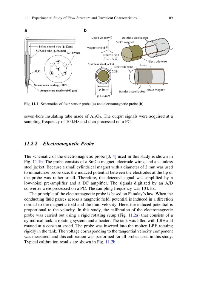
The schematic of the electromagnetic probe [3, 4] used in this study is shown in
Fig. 11.1b. The probe consists of a SmCo magnet, electrode wires, and a stainless
steel jacket. Because a small cylindrical magnet with a diameter of 2 mm was used
to miniaturize probe size, the induced potential between the electrodes at the tip of
the probe was rather small. Therefore, the detected signal was amplified by a
low-noise pre-amplifier and a DC amplifier. The signals digitized by an A/D
converter were processed on a PC. The sampling frequency was 10 kHz.
The principle of the electromagnetic probe is based on Faraday’s law. When the
conducting fluid passes across a magnetic field, potential is induced in a direction
normal to the magnetic field and the fluid velocity. Here, the induced potential is
proportional to the velocity. In this study, the calibration of the electromagnetic
probe was carried out using a rigid rotating setup (Fig. 11.2a) that consists of a
cylindrical tank, a rotating system, and a heater. The tank was filled with LBE and
rotated at a constant speed. The probe was inserted into the molten LBE rotating
rigidly in the tank. The voltage corresponding to the tangential velocity component
was measured, and this calibration was performed for all probes used in this study.
Typical calibration results are shown in Fig. 11.2b.
Al 2 O 3
Silicon resin coating(~300°C)
SUS304 tube (f3.0mmm)
Teflon coated wire (f127mm)
Acupuncture needle (f100 mm)
0.7~0.9mm
a
b
Electrode wire
SmCo magnet
Stainless steel jacket
Stainless steel jacket
2mm
3.06mm
0.21t
Liquid velocity
Magnetic field
Electric field
Electrode wire
Stainless steel jacket
SmCo magnet
4mm
Fig. 11.1 Schematics of four-sensor probe (a) and electromagnetic probe (b)
11 Experimental Study of Flow Structure and Turbulent Characteristics. . .
109
sampling frequency of 10 kHz and then processed on a PC.
11.2.2 Electromagnetic Probe
The schematic of the electromagnetic probe [3, 4] used in this study is shown in
Fig. 11.1b. The probe consists of a SmCo magnet, electrode wires, and a stainless
steel jacket. Because a small cylindrical magnet with a diameter of 2 mm was used
to miniaturize probe size, the induced potential between the electrodes at the tip of
the probe was rather small. Therefore, the detected signal was amplified by a
low-noise pre-amplifier and a DC amplifier. The signals digitized by an A/D
converter were processed on a PC. The sampling frequency was 10 kHz.
The principle of the electromagnetic probe is based on Faraday’s law. When the
conducting fluid passes across a magnetic field, potential is induced in a direction
normal to the magnetic field and the fluid velocity. Here, the induced potential is
proportional to the velocity. In this study, the calibration of the electromagnetic
probe was carried out using a rigid rotating setup (Fig. 11.2a) that consists of a
cylindrical tank, a rotating system, and a heater. The tank was filled with LBE and
rotated at a constant speed. The probe was inserted into the molten LBE rotating
rigidly in the tank. The voltage corresponding to the tangential velocity component
was measured, and this calibration was performed for all probes used in this study.
Typical calibration results are shown in Fig. 11.2b.
Al 2 O 3
Silicon resin coating(~300°C)
SUS304 tube (f3.0mmm)
Teflon coated wire (f127mm)
Acupuncture needle (f100 mm)
0.7~0.9mm
a
b
Electrode wire
SmCo magnet
Stainless steel jacket
Stainless steel jacket
2mm
3.06mm
0.21t
Liquid velocity
Magnetic field
Electric field
Electrode wire
Stainless steel jacket
SmCo magnet
4mm
Fig. 11.1 Schematics of four-sensor probe (a) and electromagnetic probe (b)
11 Experimental Study of Flow Structure and Turbulent Characteristics. . .
109