

466
7 Applications: Pebble Flow Optimizations
in nuclear engineering, the question that remained to be answered is how to design
the proper insert. This section manages to find some universal tips for the insert
design of HTGRs by trial and error and explain the underlying mechanism of the
insert effect through simulation experiments.
7.3.5.1 Outlet Diameter of Insert—d o
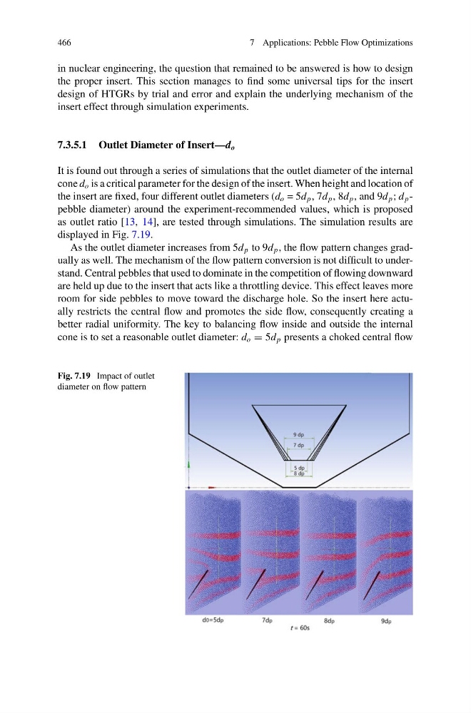
It is found out through a series of simulations that the outlet diameter of the internal
cone d o is a critical parameter for the design of the insert. When height and location of
the insert are fixed, four different outlet diameters (d o = 5d p , 7d p , 8d p , and 9d p ; d p -
pebble diameter) around the experiment-recommended values, which is proposed
as outlet ratio [13, 14], are tested through simulations. The simulation results are
displayed in Fig. 7.19.
As the outlet diameter increases from 5d p to 9d p , the flow pattern changes gradually as well. The mechanism of the flow pattern conversion is not difficult to understand. Central pebbles that used to dominate in the competition of flowing downward
are held up due to the insert that acts like a throttling device. This effect leaves more
room for side pebbles to move toward the discharge hole. So the insert here actually restricts the central flow and promotes the side flow, consequently creating a
better radial uniformity. The key to balancing flow inside and outside the internal
cone is to set a reasonable outlet diameter: d o = 5d p presents a choked central flow
Fig. 7.19 Impact of outlet
diameter on flow pattern
7 Applications: Pebble Flow Optimizations
in nuclear engineering, the question that remained to be answered is how to design
the proper insert. This section manages to find some universal tips for the insert
design of HTGRs by trial and error and explain the underlying mechanism of the
insert effect through simulation experiments.
7.3.5.1 Outlet Diameter of Insert—d o
It is found out through a series of simulations that the outlet diameter of the internal
cone d o is a critical parameter for the design of the insert. When height and location of
the insert are fixed, four different outlet diameters (d o = 5d p , 7d p , 8d p , and 9d p ; d p -
pebble diameter) around the experiment-recommended values, which is proposed
as outlet ratio [13, 14], are tested through simulations. The simulation results are
displayed in Fig. 7.19.
As the outlet diameter increases from 5d p to 9d p , the flow pattern changes gradually as well. The mechanism of the flow pattern conversion is not difficult to understand. Central pebbles that used to dominate in the competition of flowing downward
are held up due to the insert that acts like a throttling device. This effect leaves more
room for side pebbles to move toward the discharge hole. So the insert here actually restricts the central flow and promotes the side flow, consequently creating a
better radial uniformity. The key to balancing flow inside and outside the internal
cone is to set a reasonable outlet diameter: d o = 5d p presents a choked central flow
Fig. 7.19 Impact of outlet
diameter on flow pattern