

6.3 Density Difference and Loading Ratio Effects
425
Table 6.3 Parameters used in simulation
Bed
Diameter of cylinder, D (mm) 1800
Height of cylinder, H (mm)
2500
Base cone angle, α
30 o
Diameter of the discharging
hole, D o (mm)
0.5
Fuel
Particles Diameter, d p (mm)
60
Density, ρ p (kg/m3)
1846/2399.8
Total number N T
27000
Particle-particle friction
coefficients, μ p
0.3
Young’s modulus, E p (Pa)
5×10 7
Poisson rate ν p
0.3
Restitution coefficient
0.3
Wall
Particle-wall friction
coefficients, μ w
0.3
Young’s modulus, E w (Pa)
5×10 7
Poisson rate ν w
0.3
Operational
Time steps t (s)
10 −5
Circulating rate of particles
(s −1 )
1000
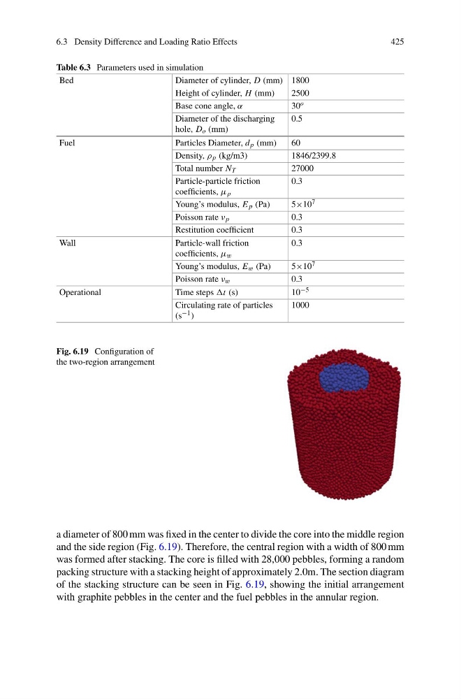
Fig. 6.19 Configuration of
the two-region arrangement
a diameter of 800 mm was fixed in the center to divide the core into the middle region
and the side region (Fig. 6.19). Therefore, the central region with a width of 800 mm
was formed after stacking. The core is filled with 28,000 pebbles, forming a random
packing structure with a stacking height of approximately 2.0m. The section diagram
of the stacking structure can be seen in Fig. 6.19, showing the initial arrangement
with graphite pebbles in the center and the fuel pebbles in the annular region.
425
Table 6.3 Parameters used in simulation
Bed
Diameter of cylinder, D (mm) 1800
Height of cylinder, H (mm)
2500
Base cone angle, α
30 o
Diameter of the discharging
hole, D o (mm)
0.5
Fuel
Particles Diameter, d p (mm)
60
Density, ρ p (kg/m3)
1846/2399.8
Total number N T
27000
Particle-particle friction
coefficients, μ p
0.3
Young’s modulus, E p (Pa)
5×10 7
Poisson rate ν p
0.3
Restitution coefficient
0.3
Wall
Particle-wall friction
coefficients, μ w
0.3
Young’s modulus, E w (Pa)
5×10 7
Poisson rate ν w
0.3
Operational
Time steps t (s)
10 −5
Circulating rate of particles
(s −1 )
1000
Fig. 6.19 Configuration of
the two-region arrangement
a diameter of 800 mm was fixed in the center to divide the core into the middle region
and the side region (Fig. 6.19). Therefore, the central region with a width of 800 mm
was formed after stacking. The core is filled with 28,000 pebbles, forming a random
packing structure with a stacking height of approximately 2.0m. The section diagram
of the stacking structure can be seen in Fig. 6.19, showing the initial arrangement
with graphite pebbles in the center and the fuel pebbles in the annular region.