

5.4 CFD-DEM Coupled Simulation and Development
317
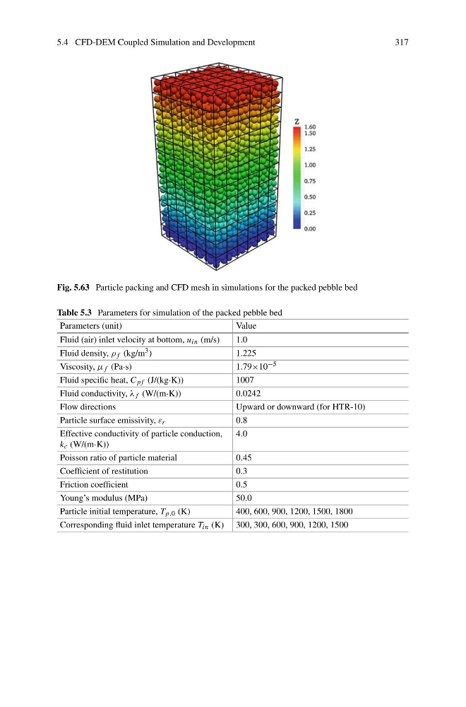
Fig. 5.63 Particle packing and CFD mesh in simulations for the packed pebble bed
Table 5.3 Parameters for simulation of the packed pebble bed
Parameters (unit)
Value
Fluid (air) inlet velocity at bottom, u in (m/s)
1.0
Fluid density, ρ f (kg/m 3 )
1.225
Viscosity, μ f (Pa·s)
1.79×10 −5
Fluid specific heat, C p f (J/(kg·K))
1007
Fluid conductivity, λ f (W/(m·K))
0.0242
Flow directions
Upward or downward (for HTR-10)
Particle surface emissivity, ε r
0.8
Effective conductivity of particle conduction,
k c (W/(m·K))
4.0
Poisson ratio of particle material
0.45
Coefficient of restitution
0.3
Friction coefficient
0.5
Young’s modulus (MPa)
50.0
Particle initial temperature, T p,0 (K)
400, 600, 900, 1200, 1500, 1800
Corresponding fluid inlet temperature T in (K) 300, 300, 600, 900, 1200, 1500
317
Fig. 5.63 Particle packing and CFD mesh in simulations for the packed pebble bed
Table 5.3 Parameters for simulation of the packed pebble bed
Parameters (unit)
Value
Fluid (air) inlet velocity at bottom, u in (m/s)
1.0
Fluid density, ρ f (kg/m 3 )
1.225
Viscosity, μ f (Pa·s)
1.79×10 −5
Fluid specific heat, C p f (J/(kg·K))
1007
Fluid conductivity, λ f (W/(m·K))
0.0242
Flow directions
Upward or downward (for HTR-10)
Particle surface emissivity, ε r
0.8
Effective conductivity of particle conduction,
k c (W/(m·K))
4.0
Poisson ratio of particle material
0.45
Coefficient of restitution
0.3
Friction coefficient
0.5
Young’s modulus (MPa)
50.0
Particle initial temperature, T p,0 (K)
400, 600, 900, 1200, 1500, 1800
Corresponding fluid inlet temperature T in (K) 300, 300, 600, 900, 1200, 1500