

3.3 Effective Thermal Diffusivity and Conductivity
143
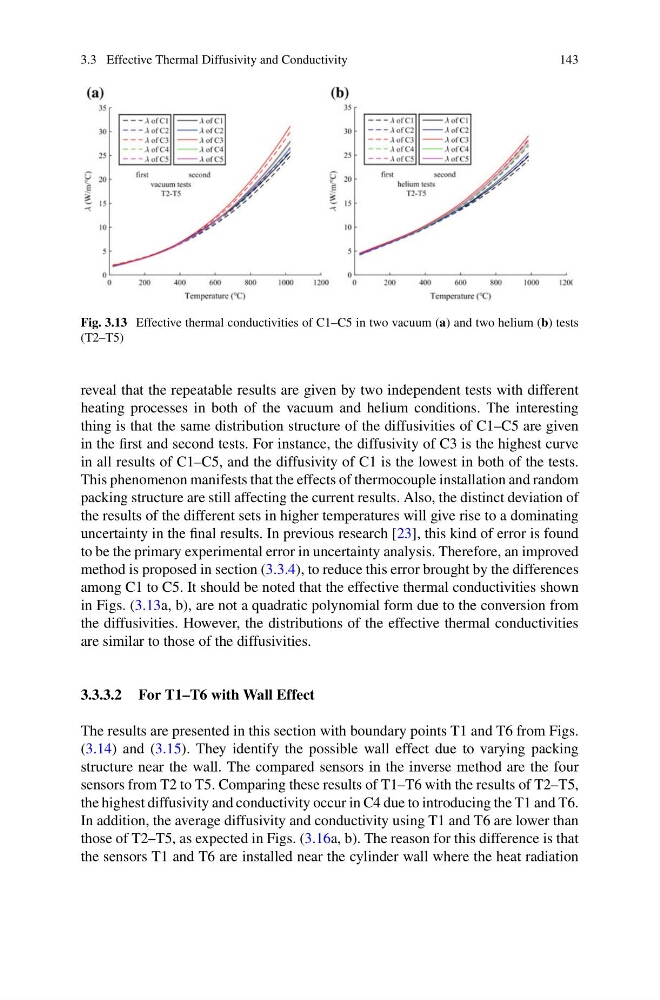
Fig. 3.13 Effective thermal conductivities of C1–C5 in two vacuum (a) and two helium (b) tests
(T2–T5)
reveal that the repeatable results are given by two independent tests with different
heating processes in both of the vacuum and helium conditions. The interesting
thing is that the same distribution structure of the diffusivities of C1–C5 are given
in the first and second tests. For instance, the diffusivity of C3 is the highest curve
in all results of C1–C5, and the diffusivity of C1 is the lowest in both of the tests.
This phenomenon manifests that the effects of thermocouple installation and random
packing structure are still affecting the current results. Also, the distinct deviation of
the results of the different sets in higher temperatures will give rise to a dominating
uncertainty in the final results. In previous research [23], this kind of error is found
to be the primary experimental error in uncertainty analysis. Therefore, an improved
method is proposed in section (3.3.4), to reduce this error brought by the differences
among C1 to C5. It should be noted that the effective thermal conductivities shown
in Figs. (3.13a, b), are not a quadratic polynomial form due to the conversion from
the diffusivities. However, the distributions of the effective thermal conductivities
are similar to those of the diffusivities.
3.3.3.2 For T1–T6 with Wall Effect
The results are presented in this section with boundary points T1 and T6 from Figs.
(3.14) and (3.15). They identify the possible wall effect due to varying packing
structure near the wall. The compared sensors in the inverse method are the four
sensors from T2 to T5. Comparing these results of T1–T6 with the results of T2–T5,
the highest diffusivity and conductivity occur in C4 due to introducing the T1 and T6.
In addition, the average diffusivity and conductivity using T1 and T6 are lower than
those of T2–T5, as expected in Figs. (3.16a, b). The reason for this difference is that
the sensors T1 and T6 are installed near the cylinder wall where the heat radiation
143
Fig. 3.13 Effective thermal conductivities of C1–C5 in two vacuum (a) and two helium (b) tests
(T2–T5)
reveal that the repeatable results are given by two independent tests with different
heating processes in both of the vacuum and helium conditions. The interesting
thing is that the same distribution structure of the diffusivities of C1–C5 are given
in the first and second tests. For instance, the diffusivity of C3 is the highest curve
in all results of C1–C5, and the diffusivity of C1 is the lowest in both of the tests.
This phenomenon manifests that the effects of thermocouple installation and random
packing structure are still affecting the current results. Also, the distinct deviation of
the results of the different sets in higher temperatures will give rise to a dominating
uncertainty in the final results. In previous research [23], this kind of error is found
to be the primary experimental error in uncertainty analysis. Therefore, an improved
method is proposed in section (3.3.4), to reduce this error brought by the differences
among C1 to C5. It should be noted that the effective thermal conductivities shown
in Figs. (3.13a, b), are not a quadratic polynomial form due to the conversion from
the diffusivities. However, the distributions of the effective thermal conductivities
are similar to those of the diffusivities.
3.3.3.2 For T1–T6 with Wall Effect
The results are presented in this section with boundary points T1 and T6 from Figs.
(3.14) and (3.15). They identify the possible wall effect due to varying packing
structure near the wall. The compared sensors in the inverse method are the four
sensors from T2 to T5. Comparing these results of T1–T6 with the results of T2–T5,
the highest diffusivity and conductivity occur in C4 due to introducing the T1 and T6.
In addition, the average diffusivity and conductivity using T1 and T6 are lower than
those of T2–T5, as expected in Figs. (3.16a, b). The reason for this difference is that
the sensors T1 and T6 are installed near the cylinder wall where the heat radiation