

A.2 Fresnel Factors for Two-Layer Model
37
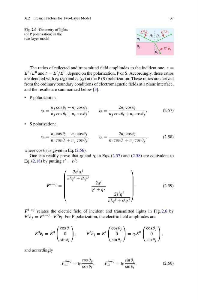
Fig. 2.6 Geometry of lights
(of P polarization) in the
two-layer model
n
n i
j
E 0 i
e
E j
e
j
i
t
E i
e
r
i
The ratios of reflected and transmitted field amplitudes to the incident one, r =
E r /E 0 and t = E t /E 0 , depend on the polarization, P or S. Accordingly, these ratios
are denoted with r P (r S ) and t P (t S ) at the P (S) polarization. These ratios are derived
from the ordinary boundary conditions of electromagnetic fields at a plane interface,
and the results are summarized below [3].
• P polarization:
r P =
n j cos θ i − n i cos θ j
n j cos θ i + n i cos θ j
,
t P =
2n i cos θ i
n j cos θ i + n i cos θ j
,
(2.57)
• S polarization:
r S =
n i cos θ i − n j cos θ j
n i cos θ i + n j cos θ j
,
t S =
2n i cos θ i
n i cos θ i + n j cos θ j
.
(2.58)
where cos θ j is given in Eq. (2.56).
One can readily prove that t P and t S in Eqs. (2.57) and (2.58) are equivalent to
Eq. (2.18) by putting ε = ε j ;
F
i→j
=
⎛
⎜
⎜
⎜
⎜
⎜
⎜
⎝
2ε i q j
ε j q i + ε i q j
2q i
q i + q j
2ε i q i
ε j q i + ε i q j
⎞
⎟
⎟
⎟
⎟
⎟
⎟
⎠
.
(2.59)
F i→j relates the electric field of incident and transmitted lights in Fig. 2.6 by
E t ˆ
e j = F i→j · E 0 ˆ
e i . For P polarization, the electric field amplitudes are
E
0
ˆ
e i = E
0
⎛
⎝
cos θ i
0
sin θ i
⎞
⎠ ,
E
t
ˆ
e j = E
t
⎛
⎝
cos θ j
0
sin θ j
⎞
⎠ = t P E
0
⎛
⎝
cos θ j
0
sin θ j
⎞
⎠ ,
and accordingly
F
i→j
xx
= t P
cos θ j
cos θ i
,
F
i→j
zz
= t P
sin θ j
sin θ i
.
(2.60)
37
Fig. 2.6 Geometry of lights
(of P polarization) in the
two-layer model
n
n i
j
E 0 i
e
E j
e
j
i
t
E i
e
r
i
The ratios of reflected and transmitted field amplitudes to the incident one, r =
E r /E 0 and t = E t /E 0 , depend on the polarization, P or S. Accordingly, these ratios
are denoted with r P (r S ) and t P (t S ) at the P (S) polarization. These ratios are derived
from the ordinary boundary conditions of electromagnetic fields at a plane interface,
and the results are summarized below [3].
• P polarization:
r P =
n j cos θ i − n i cos θ j
n j cos θ i + n i cos θ j
,
t P =
2n i cos θ i
n j cos θ i + n i cos θ j
,
(2.57)
• S polarization:
r S =
n i cos θ i − n j cos θ j
n i cos θ i + n j cos θ j
,
t S =
2n i cos θ i
n i cos θ i + n j cos θ j
.
(2.58)
where cos θ j is given in Eq. (2.56).
One can readily prove that t P and t S in Eqs. (2.57) and (2.58) are equivalent to
Eq. (2.18) by putting ε = ε j ;
F
i→j
=
⎛
⎜
⎜
⎜
⎜
⎜
⎜
⎝
2ε i q j
ε j q i + ε i q j
2q i
q i + q j
2ε i q i
ε j q i + ε i q j
⎞
⎟
⎟
⎟
⎟
⎟
⎟
⎠
.
(2.59)
F i→j relates the electric field of incident and transmitted lights in Fig. 2.6 by
E t ˆ
e j = F i→j · E 0 ˆ
e i . For P polarization, the electric field amplitudes are
E
0
ˆ
e i = E
0
⎛
⎝
cos θ i
0
sin θ i
⎞
⎠ ,
E
t
ˆ
e j = E
t
⎛
⎝
cos θ j
0
sin θ j
⎞
⎠ = t P E
0
⎛
⎝
cos θ j
0
sin θ j
⎞
⎠ ,
and accordingly
F
i→j
xx
= t P
cos θ j
cos θ i
,
F
i→j
zz
= t P
sin θ j
sin θ i
.
(2.60)